Simulating Cyclone separator with Discrete Phase Modelling in ANSYS Fluent
I. Aim: To perform analysis on cyclone separator and calculate the separation efficiency and pressure drop.
II. Introduction:
Cyclonic separation is a method of removing particulates from an air, gas or liquid stream, without the use of filters, through vortex separation. When removing particulate matter from liquid, a hydroclone is used; while from gas, a gas cyclone is used. Rotational effects and gravity are used to separate mixtures of solids and fluids. The method can also be used to separate fine droplets of liquid from a gaseous stream [1].
A high-speed rotating (gas) flow with particles is established within a cylindrical or conical container called a cyclone. Gas flows in a helical pattern, beginning at the top (wide end) of the cyclone and ending at the bottom (narrow) end before exiting the cyclone in a straight stream through the center of the cyclone and out the top. Larger (denser) particles in the rotating stream have too much inertia to follow the tight curve of the stream, and thus strike the outside wall, then fall to the bottom of the cyclone where they can be removed. In a conical system, as the rotating flow moves towards the narrow end of the cyclone, the rotational radius of the stream is reduced, thus separating smaller and smaller particles [1].
Cyclones are devices that employ a centrifugal force generated by a spinning gas stream to separate particles from the carrier gas. Their simple design, low capital cost, and nearly maintenance-free operation make them ideal for use as pre-cleaners for more expensive final control devices such as bag-houses or electrostatic precipitators. Cyclones are particularly well suited for high temperature and pressure conditions because of their rugged design and flexible component materials. Cyclone collection efficiencies can reach 99% for particles bigger than 5 μm and can be operated at very high dust loading [2].
Cyclones are used for the removal of large particles for both air pollution control and process use. Application in extreme conditions includes the removal of coal dust in a power plant and the use as a spray dryer or gasification reactor. Two parameters are of great interest in order to carry out an assessment of the design and performance of a cyclone. These parameters are the collection efficiency of particles and pressure drop through the cyclone. An accurate prediction of cyclone efficiency is very important because inaccuracy in the efficiency prediction may result in an inefficient design of the cyclone separator. CFD has a great potential to predict the flow field characteristics and particle trajectories inside the cyclone as well as the pressure drop. The complicated swirling turbulent flow in a cyclone places great demands on the numerical techniques and the turbulence models employed in the CFD codes when modeling the cyclone pressure drop [2].
In this project, CFD analysis of a tangential cyclonic separator processing air entrained with Anthracite as discrete particles is simulated and the separation process is analyzed using ANSYS Fluent Discrete Phase model(DPM). The effect of particle size and flow velocity on the cyclonic separator collection efficiency and pressure drop are studied numerically.
Some of the Empirical models for calculation of cyclone separator efficiency [2]:
Iozia and Leith Model:
Iozia and Leith logistic model is a modified version of the Barth Model, which is developed based on force balance. The model assumes that a particle carried by the vortex endures the influence of two forces: a centrifugal force, Z, and flow resistance, W. The collection efficiency `eta_i`of particle diameter d_pi can be calculated from:
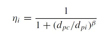
`beta` is an expression for slope parameter derived based on the statistical analysis of experimental data of a cyclone with D = 0.25 m given as

and `d_(pc)` is the 50% cut size given by Barth.
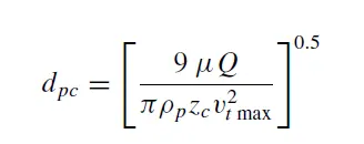
where core length, `z_c`, and core diameter, `d_c`, are given as:
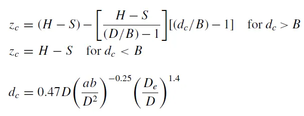
Li and Wang Model:
The Li and Wang model include particle bounce or re-entrainment and turbulent diffusion at the cyclone wall. A two-dimensional analytical expression of particle distribution in the cyclone is obtained. Li and Wang model was developed based on the following assumptions:
1. The radial particle velocity and the radial concentration profile are not constant for uncollected particles within the cyclone.
2. Boundary conditions with the consideration of turbulent diffusion coefficient and particle bounce re-entrainment on the cyclone wall are:
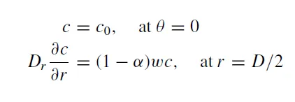
The tangential velocity is related to the radius of the cyclone by: `uR^n` = constant.
The concentration distribution in a cyclone is given as:
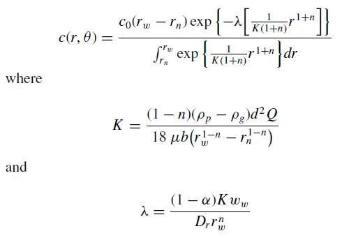
The resultant expression of the collection efficiency for particle of any size is given as:
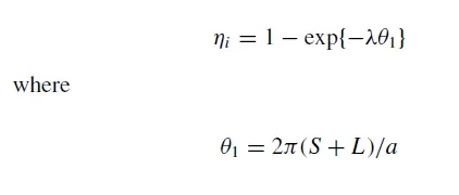
Koch and Licht Model:
Koch and Licht collection theory recognized the inherently turbulent nature of cyclones and the distribution of gas residence times within the cyclone. Koch and Licht described particle motion in the entry and collection regions with the additional following assumptions:
1. The tangential velocity of a particle is equal to the tangential velocity of the gas flow, i.e. there is no slip in the tangential direction between the particle and the gas.
2. The tangential velocity is related to the radius of the cyclone by: `uR^n` = constant.
A force balance and an equation on the particles collection yields the grade efficiency `eta_i`
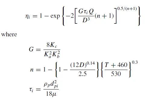
`G` is a factor related to the configuration of the cyclone, `n` is related to the vortex, and `tau` is the relaxation term.
Lapple Model:
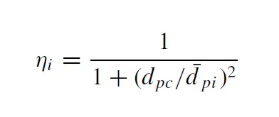
Lapple model was developed based on force balance without considering the flow resistance. Lapple assumed that a particle entering the cyclone is evenly distributed across the inlet opening. The particle that travels from inlet half-width `d_(pc)` to the wall in the cyclone is collected with 50% efficiency. The semi-empirical relationship developed by Lapple to calculate a 50% cut diameter, dpc, is
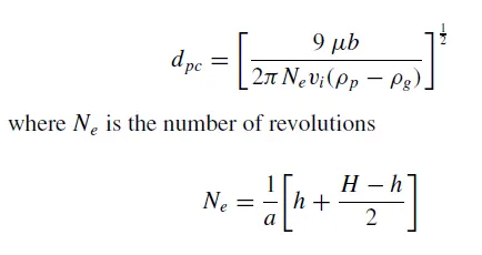
The efficiency of collection of any size of the particle is given by
III. Objectives:
- To write a few words about any four empirical models used to calculate the cyclone separator efficiency.
- To perform an analysis on a given cyclone separator model by varying the particle diameter from 1 μm to 5 μm and calculate the separation efficiency in each case. Discuss the results. [Use both the velocities as 3m/sec.]
- To perform an analysis on a given cyclone separator model by varying the particle velocity from 1 m/sec to 5 m/sec and calculate the separation efficiency and pressure drop in each case. Discuss the results. [Use particle diameter size as 5 μm for all cases & keep flow velocity same as particle velocity].
IV: Solving & Modelling approach:
3D CFD analysis is carried out in Ansys workbench using Fluent solver to simulate the Anthracite particles separation from air in a cyclone separator.
V: Pre-processing and solver setting:
The first step in a CFD analysis is preprocessing. This includes preparing the geometry/ computational domain, discretization of the domain (meshing), assigning material properties, boundary conditions, solver setup.
1. Geometry/Domain:
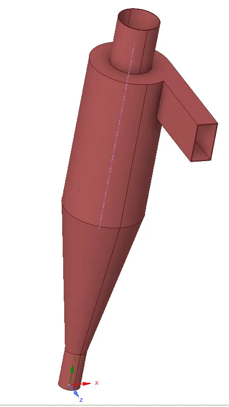
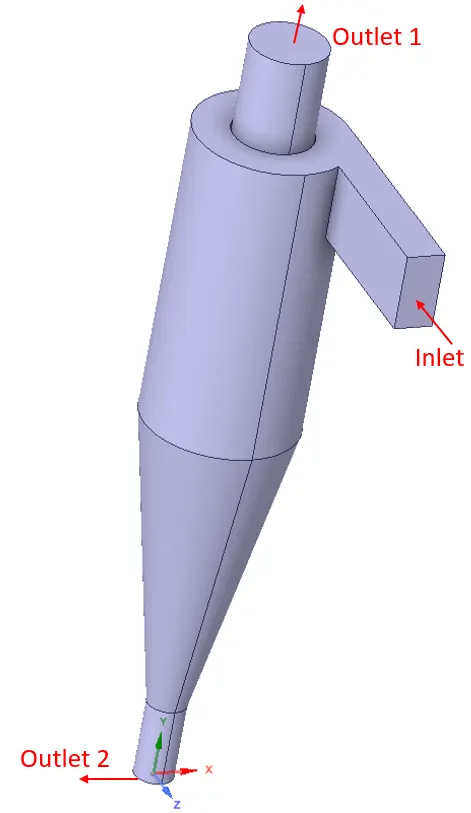
A 3D solid geometry of a typical tangential cyclonic separator is imported into SpaceClaim. Then using the volume extraction option in the SpaceClaim, the fluid domain is extracted. The geometry (casing) of the separator is suppressed for physics after fluid domain extraction. The following figures show the cyclone separator geometry and extracted fluid domain.
| Cyclone Separator Geometry | Extracted Fluid Domain | Computational mesh |
 |
 |
 |
2. Domain discretization /Meshing:
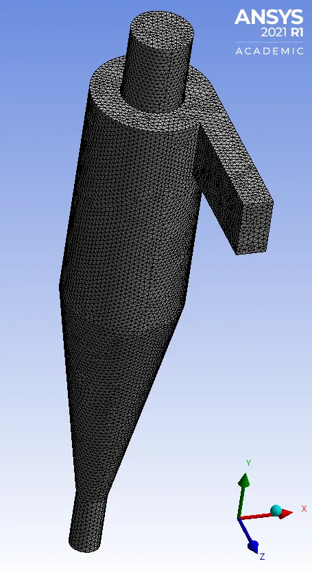
The 3d fluid domain is discretized into a finite number of control volumes using the Ansys meshing component. A 3D tetrahedral mesh is created for the fluid domain to accurately capture the geometry. A global element sizing of 8 mm is applied to the casing, keeping all other settings to Ansys meshing defaults. The generated computational mesh is shown in the above figure.
The generated 3D mesh has a cell count of 184727 with average element quality of 0.837 and minimum Orthogonal Quality = 4.21423e-02.
The boundaries of the domain are also defined in the Ansys mesher using the named selection option. The boundaries are defined as follows:
| Boundary/Zone | Boundary/Zone name |
| Tangential Inlet | inlet |
| Top Outlet | outlet 1 |
| Bottom Outlet | outlet 2 |
3. Solver setup:
The 3D analysis is performed on the discretized domain(meshed model) in Ansys Fluent CFD software. A double-precision parallel solver with 4 cores is used. The double-precision solver uses 64-bit precision, which reduces the round-off error in the results. The solver setup details are given below:
| Solver type | Steady-state pressure-based solver |
| Gravity effect | '-ve' Y-direction, 9.81 m/sec^2 |
| Turbulence model | k-ε">RNG k-ε model with swirl dominated flow and standard wall functions |
| Fluid domain | Air (default Ansys fluent properties) |
| Pressure - Velocity Coupling | Coupled |
| Residual Monitors Criteria | 1E-03 for all the governing equations |
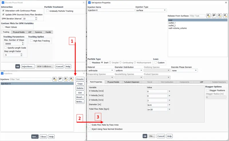
The cyclone separator efficiency is measured in terms of particles trapped at the bottom of the separator. For this inert Antracite particles are injected into the flow domain at the inlet boundary using the Discrete Phase Model (DPM model). The DPM model settings for the analysis ae shown below:
The cyclone separator efficiency and pressure drop is analyzed for different flow conditions and particle sizes as given below:
| Discrete Particle size (μm) | Discrete Particle Velocity (m/sec) | Inlet flow velocity BC (m/sec) | Outlet Pressure BC (Pa) | |
| Case 1 | 1 | 3 | 3 | Zero gauge pressure |
| Case 2 | 3 | 3 | 3 | Zero gauge pressure |
| Case 3 | 5 | 3 | 3 | Zero gauge pressure |
| Case 4 | 1 | 1 | 1 | Zero gauge pressure |
| Case 5 | 1 | 5 | 5 | Zero gauge pressure |
The particles are injected at the inlet BC as a surface injection with the discrete phase BC option set to reflect. The discrete phase BC at outlet 1 BC is set to escape. The discrete phase BC at outlet 2 is set to trap, in order to track the number of particles separated from the gas by the separator.
IV Solution:
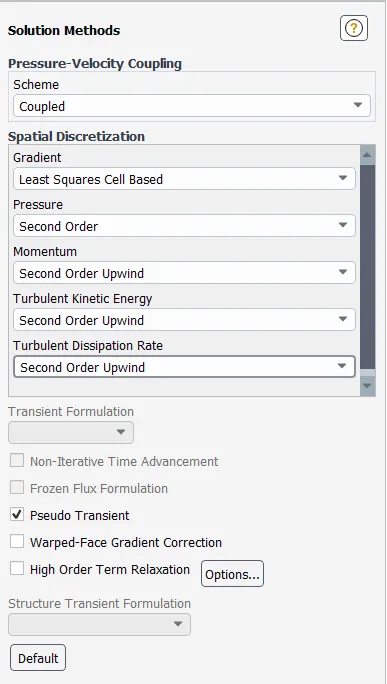
The solution is initialized with standard initialization computing flow variables from the inlet BC. The solution is solved for 600 iterations. Rest all settings are ANSYS Fluent defaults for the steady-state solver.
VI Results:
The particles injected at the inlet surface get carried away by the flow gas into the cyclone separator. Due to the swirl created by centrifugal forces and the effect of gravity, most of the particles settle to the bottom of the separator. The vortex created due to centrifugal forces aid this separation of denser particles from the less dense flow gas. The light gas flows out of the domain through outlet 1 and particles get trapped at outlet 2. The effect of flow velocity, particle injection velocity, and particle diameter on the cyclone separation efficiency and pressure drop is discussed below:
The following animation shows the movement of the particles in the cyclone separator for a particle size of 1 μm and inlet velocity of 5 m/sec. The swirl motion attained and vortex created due to centrifugal forces can be seen. It can be obserevd that most of the particles gets seperated from the gas and settle at the bottom of the seperator (outlet 2). Some particles continue in the flow the gas through the outlet 1 and some gets trapped in recirculation zones as obsereved in the below animation.
The efficiency of the separator depends on the design, flow velocity, and particle sizes. The separation efficiency and pressure drop for various particle sizes and flow velocities are summarized in the table below:
| Particles injected | Particles trapped at Outlet 2 | Separation Efficiency (%) | Inlet Pressure (Pa) | Outlet Pressure (Pa) | Pressure drop (Pa) | |
| case 1 | 172 | 44 | 25.58 | 20.6084 | 0 | 20.6084 |
| case 2 | 172 | 147 | 85.47 | 21.0632 | 0 | 21.0632 |
| case 3 | 172 | 171 | 99.42 | 21.0632 | 0 | 21.0632 |
| case 4 | 172 | 25 | 14.53 | 1.83888 | 0 | 1.83888 |
| case 5 | 172 | 60 | 34.88 | 59.2056 | 0 | 59.2056 |
The efficiency is calculated based on the ratio of particles trapped at outlet 2 to the total number of particles injected at the inlet. The particles injected and trapped are extracted from Fluent injection tracking results.
The efficiency increases as the flow velocity increases as well as the particle size for the current separator design. The efficiency was found to be highest (99.48%) for a particle size of 5 μm and velocity of 3 m/sec. Also the pressure drop was more with increased inlet velocity.
Conclusion:
In this project , the seperation of anthracite particles in a flow gas in a cyclone separator is simulated using DPM in Ansys Fluent. The separation efficiency and pressure drop is estimated for different particle sizes and flow velocities. It was obserevd for the current separator design the effciciency was highest for a particle size of 5 μm and flow velocity of 3 m/sec case.
References: