Week 8: Proportional Valve simulation
Aim - Proportional Valve simulation in Converge 3.0
Introduction - A Proportional valve is used as a safety device in systems where the machines interact with high pressures. The protection is done by preventing pressure exceeding the desired limit in a process system by releasing a volume of fluid from the process when a predetermined maximum pressure is reached thereby reducing excess pressure.
Proportional valve / Safety relief valve
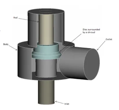
Geometry -
- Geometry creation-
- Drag-drop
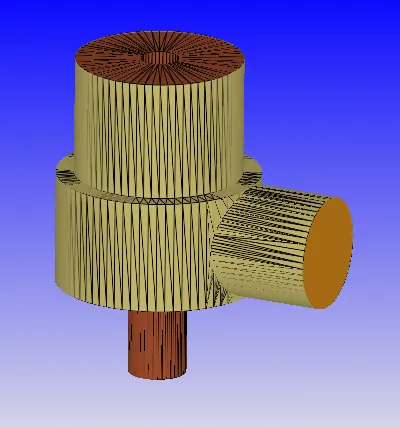
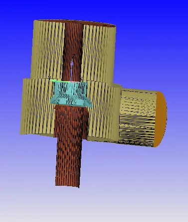
- Boundary Flagging
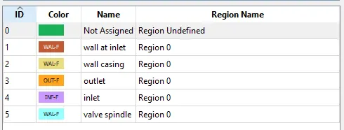
- Boundaries were defined using the Boundary function
- 5 different boundaries were defined as follows -
- Steady State Cases
Case Setup
- Application type > Time-based
- Materials> Select Predefined mixture "Air"
- O2 and N2 Gas species added
- Simulation parameters
- Run Parameters -
- Steady State
- Simulation time parameters - 15000Cycles
- Transient -
- Simulation time parameters - 1.6s
- Steady State
- Solver parameters - Density-based NS solver
- Run Parameters -
- Boundary conditions-parameters assigned as follows
- Inlet -
- SS Case - Inflow Type-3000000Pa. 300K, Air Species
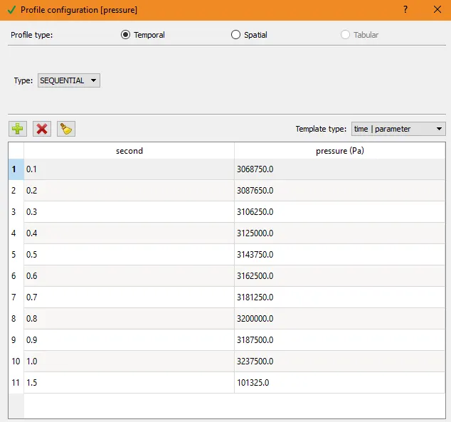
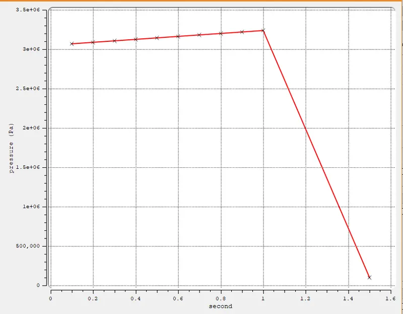
- FSI Case - Inflow Type - Inlet Pressure file -
- Outlet - Outflow Type-101325Pa. 300K. Air Species
- Wall Inlet / Casing / Valve casing - Wall - No Slip
- Valve casing - Wall -
- Steady-state case - No-Slip
- Transient case - Law of wall - FSI motion
- Inlet -
- Initial Conditions and Events
- Region and initialization Add Volumetric Region with Air species. Initial pressure-Inlet pressure - 101325.0Pa. 300K.
- Physical Models -
- Turbulence Model - RNG-k-e
- Transient cases only - FSI -
- Valve spindle boundary added as FSI object
- Forces acting on spindle = -7126N
- 1DOF in z-direction - spindle axis
- Grid Control
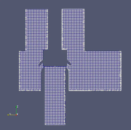
- Base Grid - 0.004x0.004x0.004 m
- Output/Post-processing
- Time interval 3D O/p files - 100cycs(ss) / 0.015s(FSI)
- Advanced Parameters
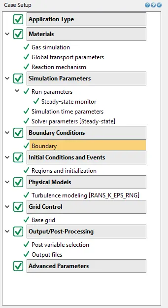
- Steady State Cases
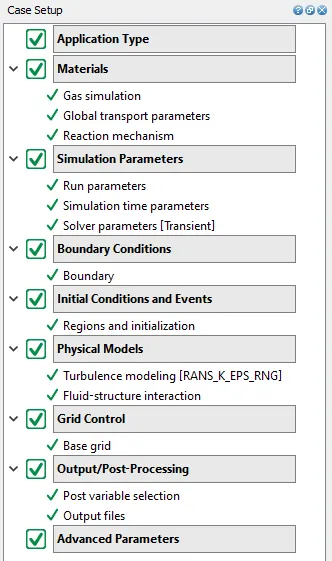
- Transient FSI Case
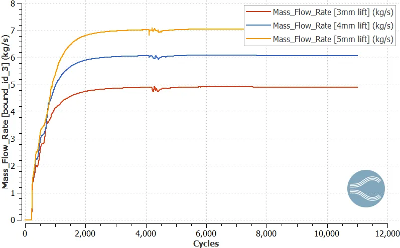
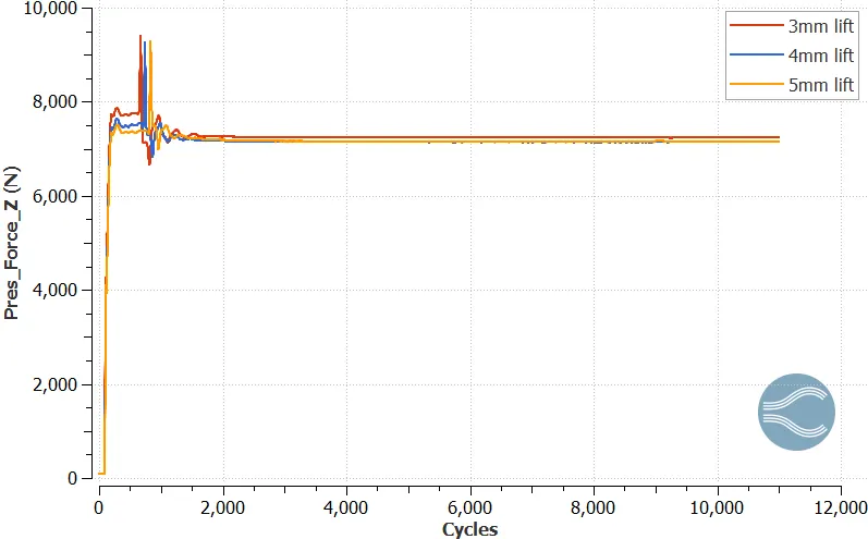
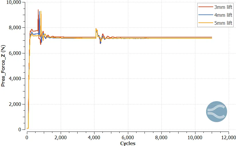
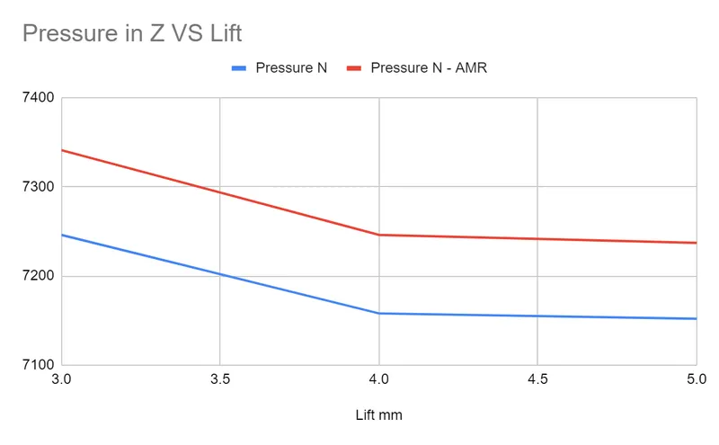
Observations - After running the calculation on Cygwin following are the results observed in Paraview and Converge Line plotting tool. We observe that as the lift increase the velocity and mass flow rate increases & the pressure on the spindle decreases. Also, the total pressure in the system/valve increases as the lift increases. The AMR results are more close the actual/practical value since the mesh is refined as compared to without AMR.
- Mesh
-
- Velocity
- Without AMR
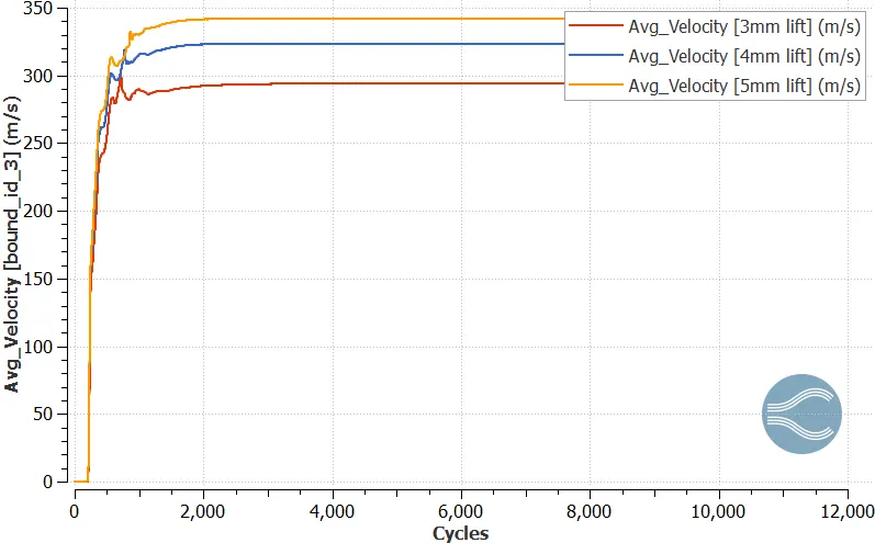
- As lift velocity, the mass flow rate increases.
- With AMR
-
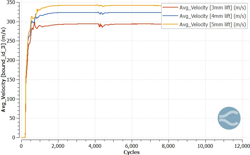
- Pressure
- Without AMR
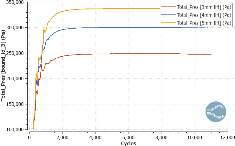
- The total pressure in the system/valve increases as the lift increases
- With AMR
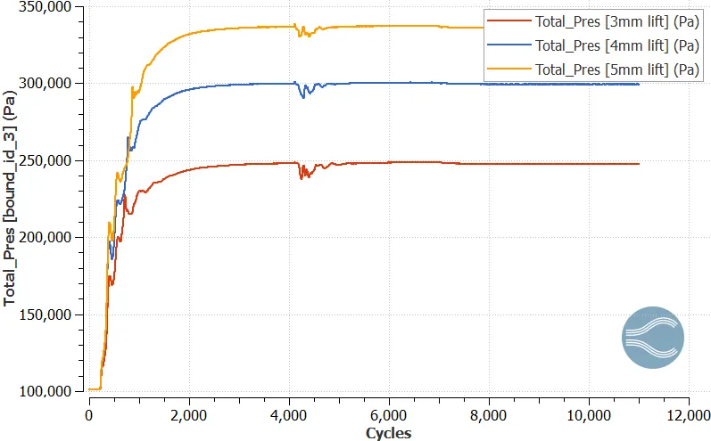
- Mass flow rate
- Without AMR
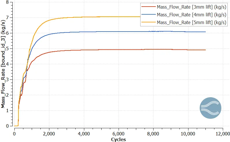
- As lift increases, the mass flow rate increases.
- With AMR
- Pressure force along Z - decreases as the lift increases
- Without AMR
- With AMR
- Pressure on spindle Vs Lift
- FSI Model - the following results are obtained in converge line plotting - fsi object
- Spindle position
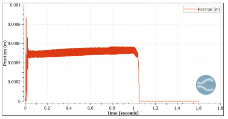
- We observe the alternating nature of the valve spindle meaning the spindle is moving up & down & this happens because when the spindle valve moves its basic relief the pressure & because of this the pressure reduces to a point were the spring force & mass of the valve dominates which basically pushing the valve back to his position. Also, the amplitude of the valve spindle increase with respect to time but after one second the pressure get reduced to its initial pressure & the valve spindle back to its original position & this sudden drop in pressure is because the pressure profile which we have given at the inlet.
- Force on Spindle
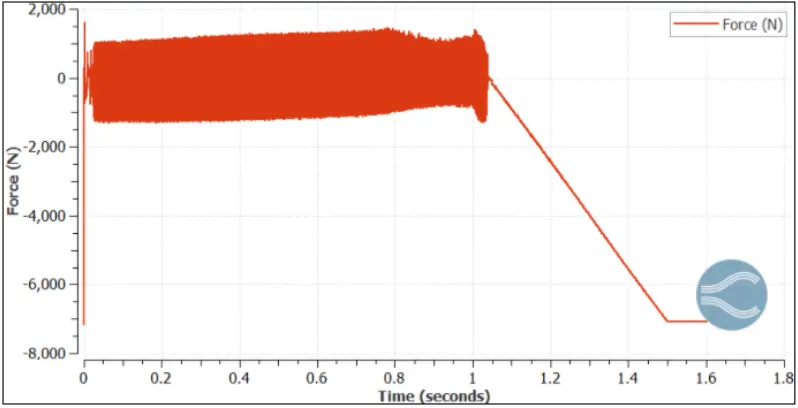
- We see that the force exerted by the valve spring is 7126 N which was given in the FSI settings, now initially the valve is opened by fluid force. After a certain while it goes to 7126 N again as the pressure becomes to the default setting in the BC. The negative sign indicates the force is acting downwards, which is against the flow of fluid,
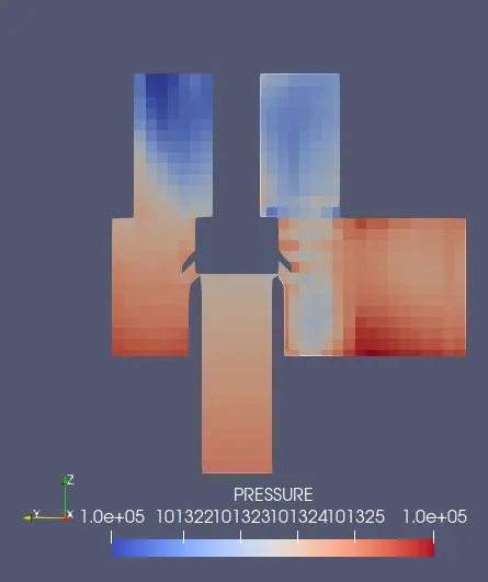
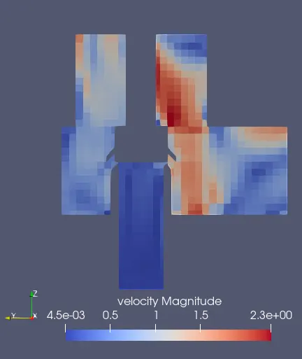
- Animation link - https://youtu.be/k4OnwNaD-x4 , https://youtu.be/vs9cUdsu1d0
-
Conclusion -
- All required results of proportional value were observed.