Week 8 - Natural Convection-II
Aim: To perform natural convection analysis for given Low voltage control panel.
Geometry:
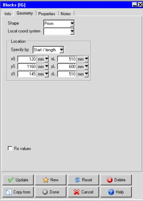
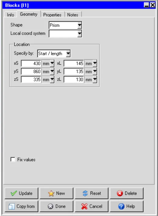
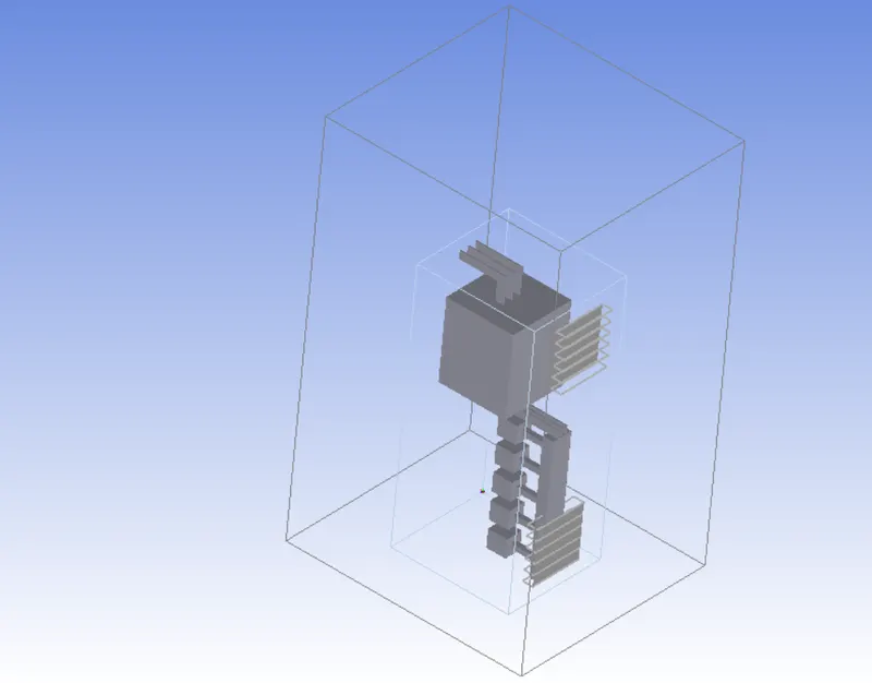
The Low voltage control panel contains circuit breaker,Bus bars and cable. The boundary information were given and have followed accordingly. I have created everything with help of “blocks” and used standard values which is closest to original model dimension. I have shown all model dimensions and final icepak model below,
Circuit Breaker(IG)
Circuit Breaker(I1)
Placed “Grills” left side of the enclosure. Considered bottom grill as Normal in and top grills as Normal out and used free area ratio is 1.
Final Model
Mesh:
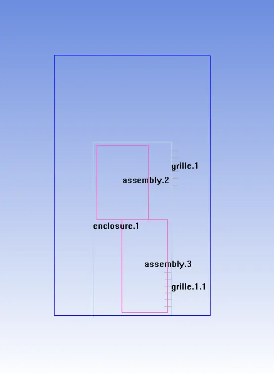
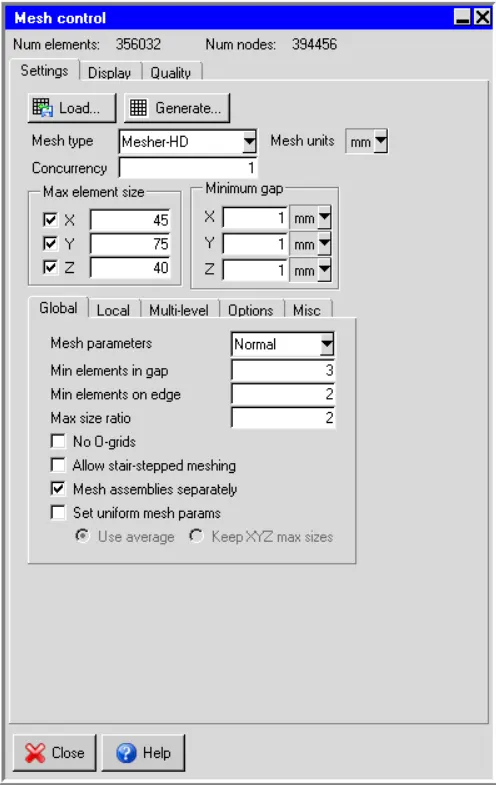
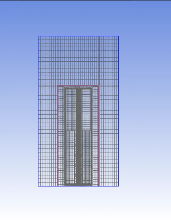
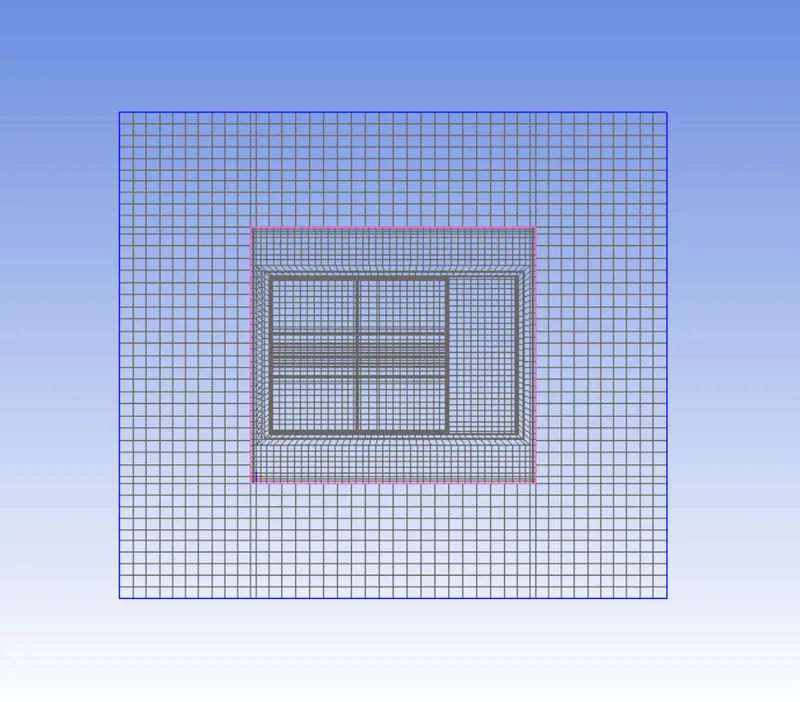
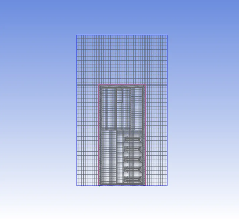
The mesh count has reduced with help of non-conformal meshing and checked visual and quality inspection.
Mesh Quality
Face Alignment : 0.541228(Min)
Voulme : 2.96296e-10(Min)
Skewness : 0.43914(Min)
Non-Conformal mesh assembly
Mesh Control
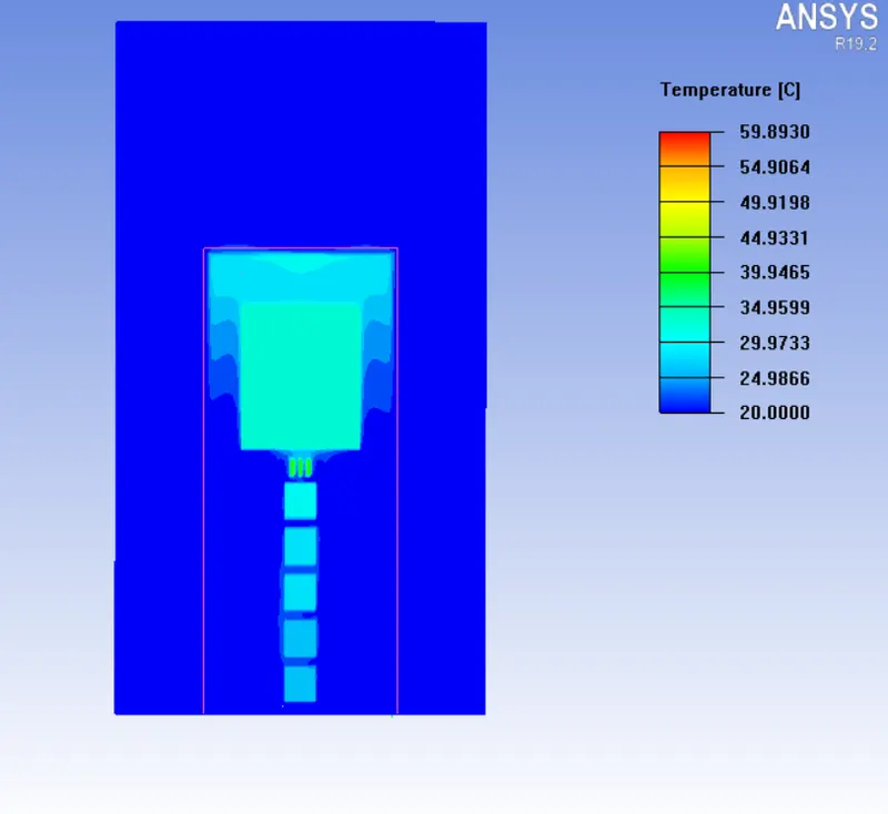
X-Axis cut plane
Y-Axis Cut plane
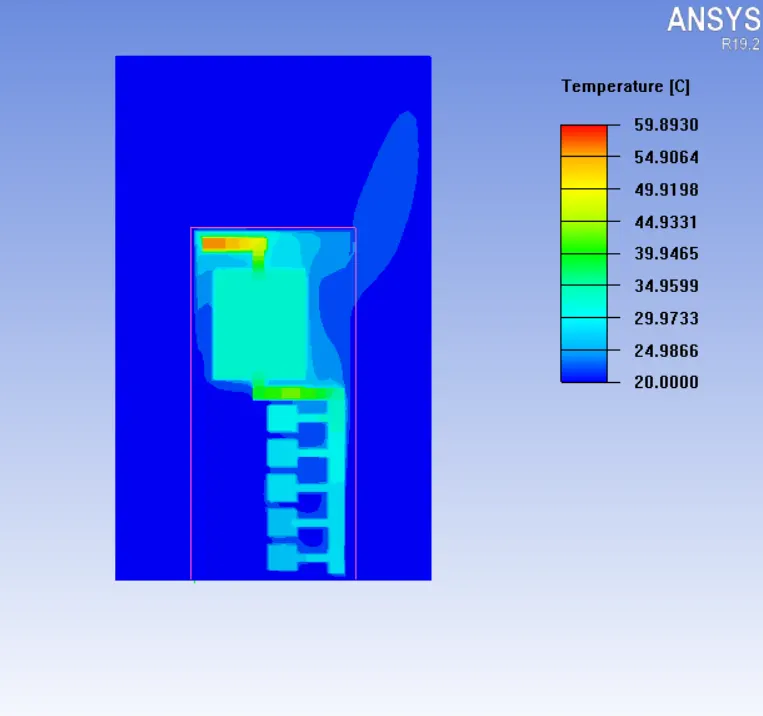
Z-Axis cut plane
Solver Setting:
Basic Parameters
Variable Solved : Flow,Temperature
Radiation : OFF
Flow regime : Turbulent-Zero equation
Natural convection : Gravity Vector- Y(-9.80665m/s2)
Used Default material values
Used Steady state analysis
Solution Initialization : 0 m/s
Boussinesq eqaution : Operating pressure - 101325N/m2
Basic Setting
Numer of iteration:300
Convergence Criteria: Flow(1e-5), Energy(1e-7), Joule heating (1e-7)
Parallel Setting
Parallel processor : 4
GPU used : 1
Specify moitor point output frequency : 10
Enabled autosave interval
Advanced Setting
Discretization scheme
Pressure- First
Momentum - First
Temperature - First
Under relaxation
Pressure- 0.3
Momentum - 0.7
Temperature - 1.0
Viscosity - 1.0
Body forces - 1.0
Linear Solver
Pressure - Type(V), Termination criterion(0.1), Residual reduction tolerance(0.1), Stabilization(None)
Momentum - Type(flex), Termination criterion(0.1), Residual reduction tolerance(0.1)
Temperature - Type(F), Termination criterion(0.1), Residual reduction tolerance(0.1), Stabilization(None)
Joule heating - Type(F), Termination criterion(1e-6), Residual reduction tolerance(0.1), Stabilization(None)
Used double precision
Post Processing:
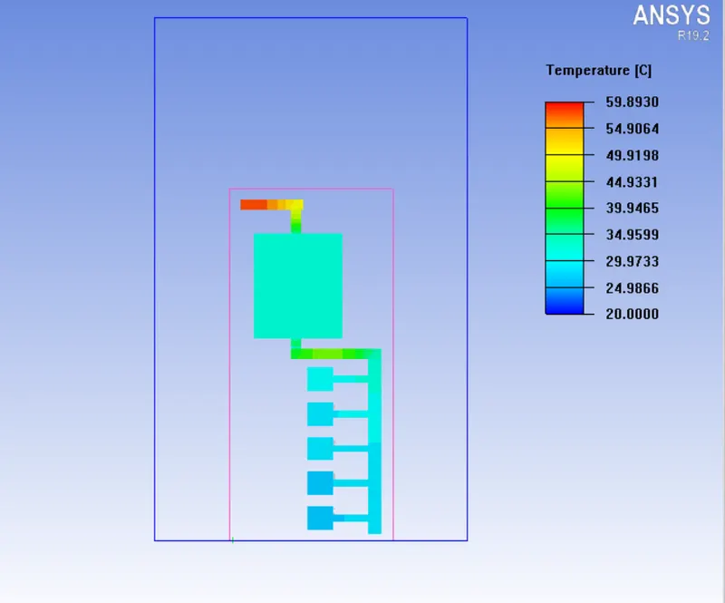
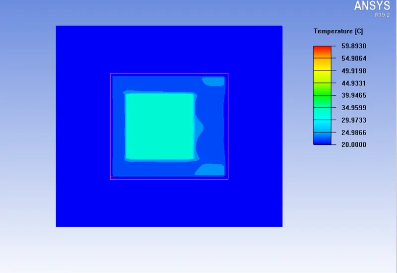
The obtained plots are plotted here. Here, We can see max temperature rise(59 degree) attained near "IG" Circuit breaker even though placed grill is near the circuit breaker and see expected temperature rises on other circuit breaker and bus-bars.
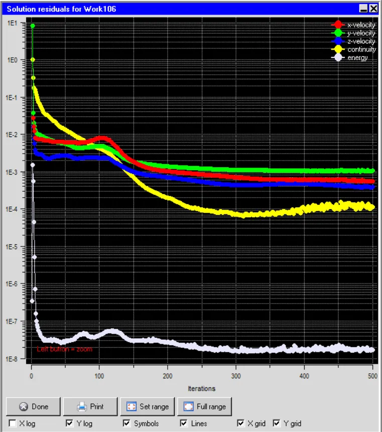
Residual plot
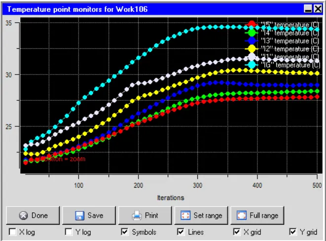
Monitor Points on Circuit breaker
Contour temperature plot by object face(node)
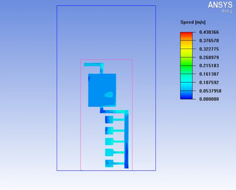
Contour Speed plot by object face(node)
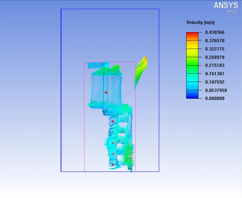
Vector Velocity magnitude plot by object face(Node)
X-axis cut plane temperature plot:
Y-Axis cut plane temperature plot:
Z-Axis cut plane temperature plot:
Result Summay:
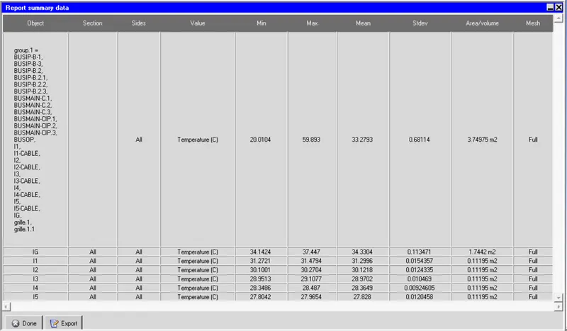
Conclusion:
We are successfully performed thermal analysis for Low Voltage control panel and shown max temperature rise inside the panel.