Week - 8 - Morphing
Aim: Understanding the Basics of MORPHING in ANSA and its industrial applications.
Introduction: Mesh morphing consists of the adaption of a computational grid adopted for computer aided engineering (CAE). For instance, the solid or shell mesh of a structural part ready to be processed by an FEA solver, or the volume mesh complete with boundary conditions for a CFD solver, can take a new shape by just updating nodal positions. This means that the topology of the mesh (nodes count, cells count, connectivity) stays the same. Only the x,y,z coordinates of the nodes in the part of the model undergoing a shape modification are updated.Usually mesh morphing is faster than remeshing for a number of reasons: it avoids “remeshing noise” (having the same mesh adapted means the effect of a parameter is not confused with the effect of a new mesh structure), so variation effects can be assessed even with a coarser mesh. The CAE model can be updated on the background keeping all the original settings (boundary conditions). The update of nodal positions usually requires less computational efforts vs a full mesh regeneration. Creating shape parameters with mesh morphing is faster than creating a parametric CAD model.[2]
Uses: Mesh morphing can be used for different purposes: create shape parameters (i.e. change a length, an angle a thickness), move onto a new known shape (i.e. as manufactured, as designed by CAD), move onto a shape predicted by the CAE solution (automatic shape optimization with adjoint or BGM), and/or support multiphysics (move CFD mesh according to the evolution of the FEM-connected one, enable erosion/deposition).
Morphing Methods:
- Direct morph
- Box morph
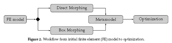
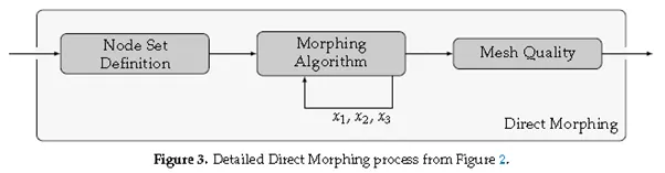
Direct Morph: Each Direct Morphing process consists of three subprocesses. First, we define the nodes for the three different node types Control nodes are points in space, that impose a given displacement, free nodes are nodes of the FE mesh that are free to move and fixed nodes are points in space that stay at their locations during the morphing process. Next, we apply the actual morphing algorithm onto the set of free nodes and receive their new coordinates. This is done separately for the three directions x1, x2 and x3. This results in the preliminary morphed mesh. Mesh quality criteria indicate where node relaxation or remeshing is necessary in a last step, resulting in the final morphed mesh.
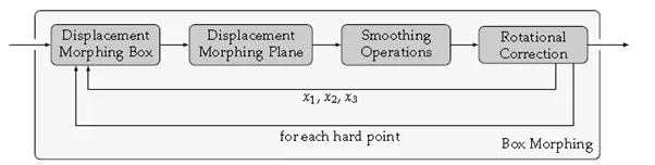
Box Morph: The Box Morphing approach is also referred to as free-form-deformation (FFD). Other than the Direct Morphing approach, Box Morphing does not act directly on the FE nodes. To deform the original geometry, first a box structure must be created. In case the structure only
consists out of parallelepipeds, the used approach is the FFD. In the case that more complex volumes, such as e.g., prismatic ones, are used, the approach is called extended-free-form-deformation(EFFD). Since the Box Morphing approach is considered Indirect Morphing, the used control points are not situated on the FE mesh itself, but are defined in the box structure.
Benefits:
- Minimizes time in design modification by directly working at mesh level thus improves the overall lead time
- Automatic control block creation methods requires less skill and effort, avoiding high expertise, leading to time reduction in development and design
- Fast and efficient design creations using parameterized optimization
- Easy morphing of CAE models from parent design to a new concept or to match design specifications for two components derived from different parent designs
- Creation of ‘n’ number of parameters for different designs, enabling easy trial and error method of design correction[3]
Applications:
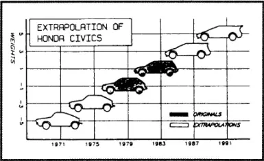
- Design Optimization: There are many strategies of optimisation, but a common feature of design optimisation of any product or system involves generating a feasible design followed by the performance evaluation of the design. The morphing technique would be undoubtedly useful in this process by offering a relatively painless method of generating a vast number of design alternatives rapidly. In form design this capability can be used to generate a large number of predictable models from a set of given ‘parent’ forms. Although the morphing technique holds significant potential for rapid generation of shapes, little attention has been given to the application of morphing for product design so far. Below Figureshows an example of generating future/retrospective models (1971, 1975, 1987, and 1991) from existing two Honda Civic models (1979 and 1983) through extrapolation.[1]
2.Vehicle developmemt:A mesh modification approach based on morphing technology was developed to address the challenge of fast re-analysis of modified structures without the need of changing the CAD model. The approach enables the evaluation of design concepts starting from the morphed predecessor models, allowing validated solutions to be incorporated in the first version of the CAD model. Different styling variants can be rapidly evaluated, matching the development time and cost constraints of OEMs. Different styling variants can be rapidly evaluated, matching the development time and cost constraints of OEMs.[4]
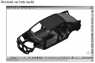
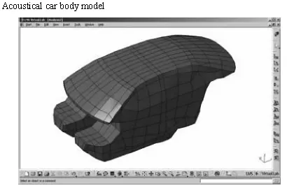
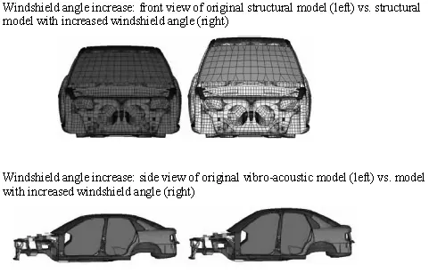
3. Windshield angle increase: A second design study involves a change in windshield angle, resulting in an increased vehicle height (10%) without affecting the lower body structure. This modification was implemented in the structural and acoustic models and the effect on the vibro-acoustic performance.[4]
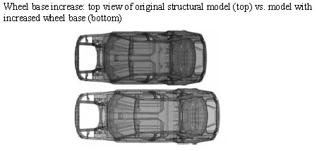
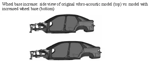
4. Wheel base increase:
Procedure:
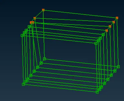
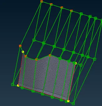
- In the MORPH deck, select the geometry or FE using New.
- Here we can select ortho or volume box.
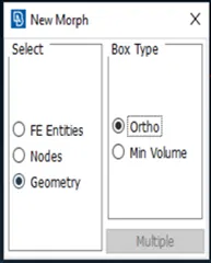
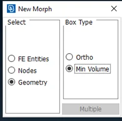
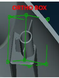
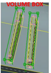
- Now using the move command we can drag it to desired distance.
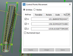
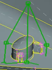
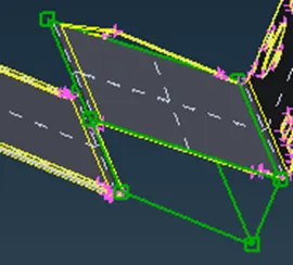
- Using the split command we can split the Box, and can control the certain section of area.
Conclusion: Learnet the basics of Morphing and its industrial use
References:
- https://www.sciencedirect.com/science/article/pii/S2092678216303442
- www.Google.com
- https://www.depusa.com/meshworks/modules/cae-morphing/
- https://www.researchgate.net/publication/264818639_Application_of_mesh_morphing_technology_in_the_concept_phase_of_vehicle_development