Week 8 Challenge
AIM : TO CALCULATE THE CENTRIFUGAL FORCE OF THE CLASS 70R LOADING VEHICLE AND APPLY THE LOAD ON THE BRIDGE AND ANALYSIS OF THE BRIDGE USING ATAAD PRO
INTRODUCTION :
- In this challenge i have to calculate the centrifugal force of the vehicle
- I created the model using given data and some modification i created in the model
- Vehicle defination have to give properly
ASSUMPTIONS :
- Height of the pier is 10m.
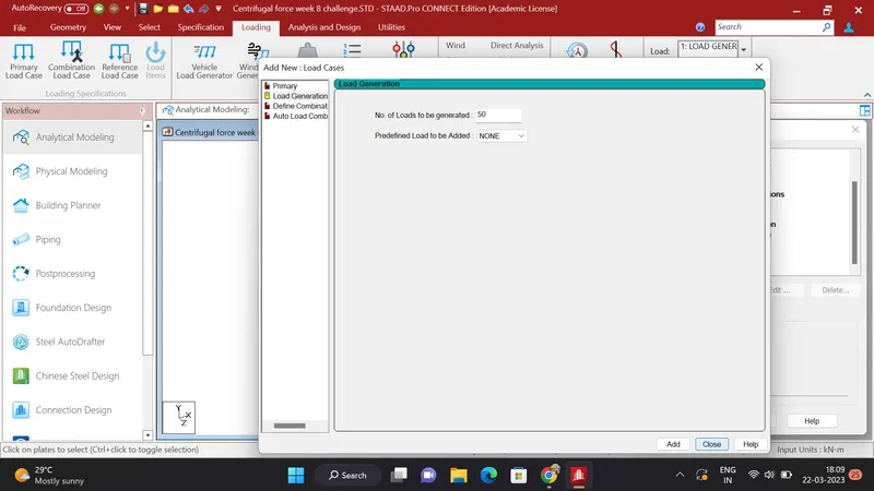
- Load generation is 50
- All the components made of the concrete
GIVEN DATA :
- Span of the bridge : 12m
- width pf the bridge 7m
- live load of class 70R laoding
- Design speed 75km/hr
- Radius of curvature : 3m
CALCULATION :
Centrifugal Force : C :
W X V X V / 127R
70 X 75 X 75 / 127 X 3
C = 930KN
PROCEDURE TO MAKE A MODEL AND ANALYSIS OF MODEL :
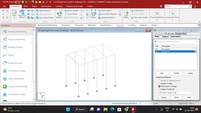
1. Create a beams , piers and deck slab of the structure
- Add a node 0,0,0 and another node at the 10m height below the first one
- Add a beam between this nodes and using translational repeat create copy of this beam in Z direction at a distance of the 7m
- select this two beams and using translational repeat copy this beams in X direction at a spacing of 3m and of 5 steps
- Add a beam between this beams and create cross beams
- Select the one corner node and copy this in X direction and select both and copy this nodes in Z direction at a distance of the 0.5 m and create a plate
- The structure will ooks like below
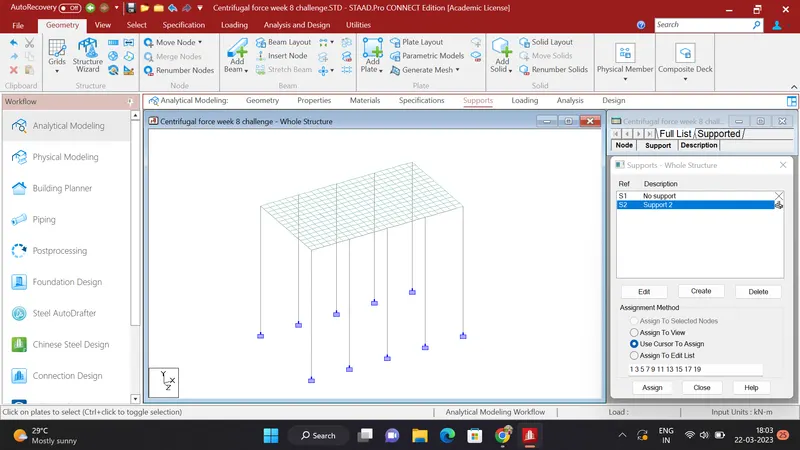
2. Add a support to the piers :
- Select the plate and by using the translational repeat copy the plate in X direction having 23 steps and in Z direction of 13 steps at a distance of 0.5
- add a fixed support and assign this support to the bottom nodes of the pier
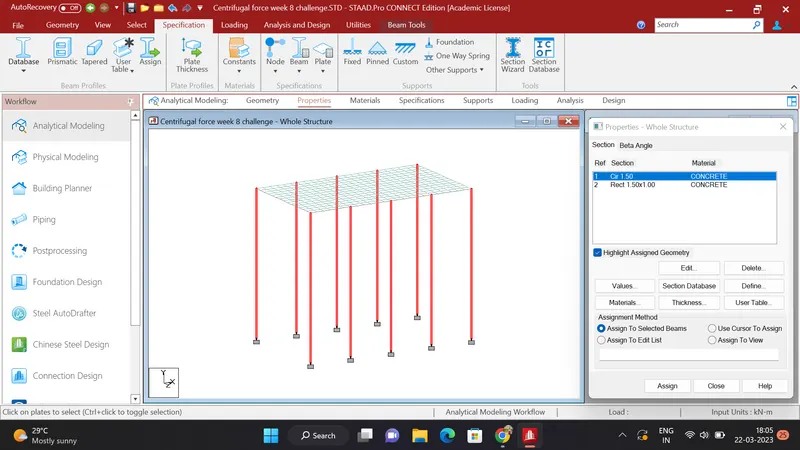
3. Assign the properties to the each component :
- Click on properties click on create and add a properties of circle 1.5m diameter and rectangle of 1.5 X 1m and plate thickness of the 0.5m
- This all are consist of concrete
- Click on circuler property and assign this property to the pier
- Click on the rectangle property and assign te property to the all the beams
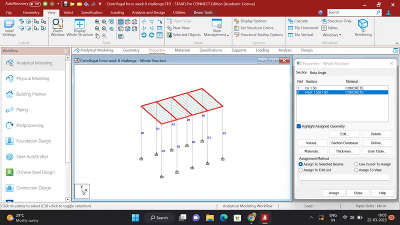
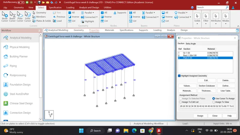
- Assign the plate thickness property to the all the plates
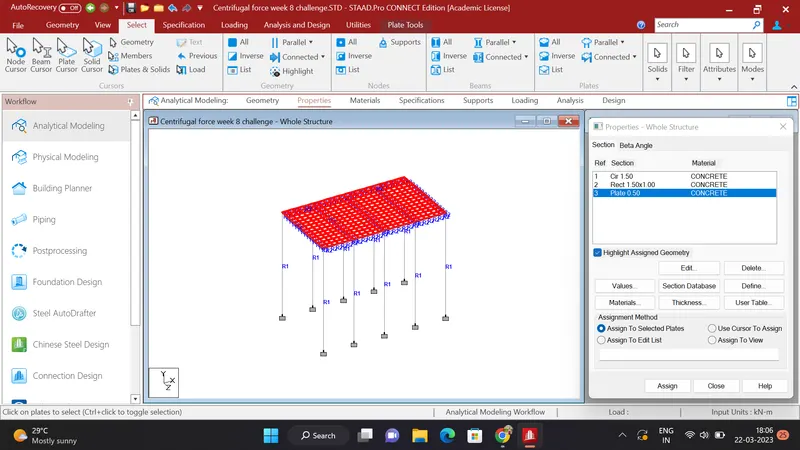
- All the properties assigned to the structure
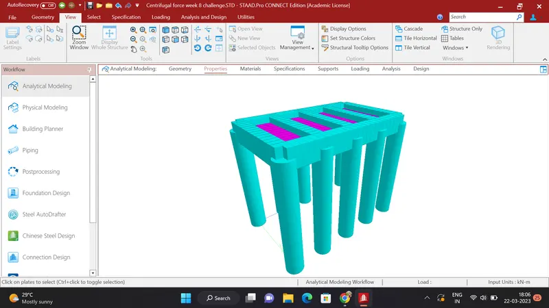
- In the 3D rendering our structure will look like this
4. LOADING DEFINATION
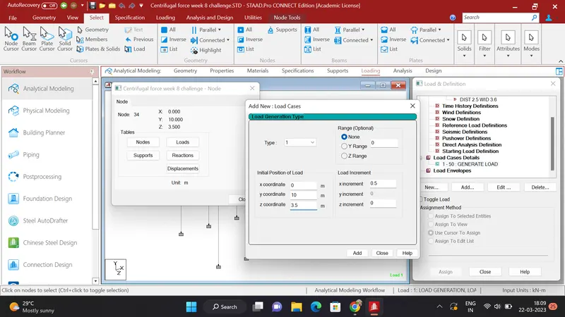
- Click on loading - Defination - add - vehicle defination add the laod we calculated in above calculation shown in below
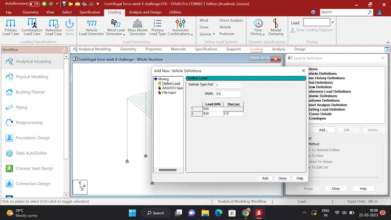
- Click on load case details and add a load generation 50 assumed add and close the box
- click on added case and add and give a details where the load case starts
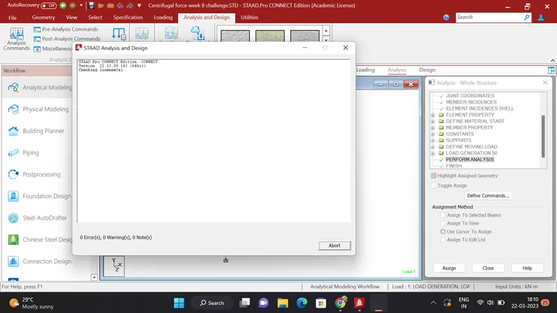
- Click on analysis and run the file
5. RESULTS :
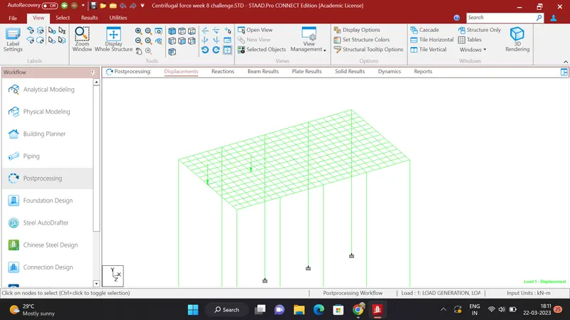
- Deflection :
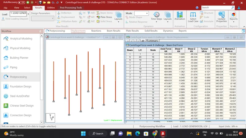
- BEAM END FORCES OF THE PIERS :
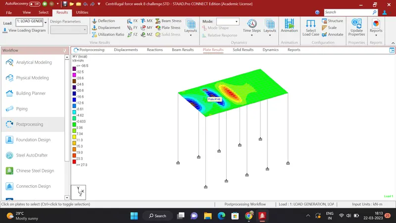
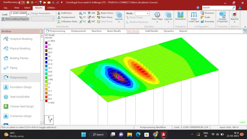
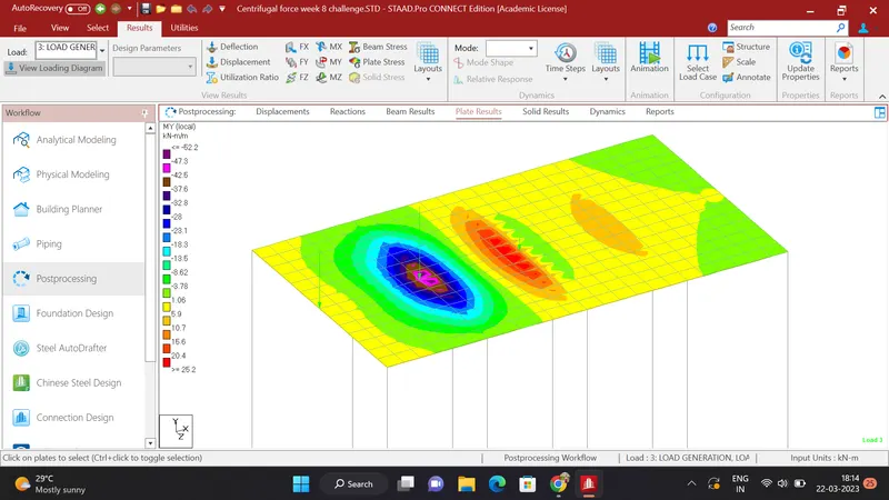
- PLATE RESULTS IN MY DIRECTION :
FINAL RESULT
THE DEFLECTION BENDING MOMENT AND SHEAR FORCE IS DIFERRENT FOR THE DIFFERENT LOAD GENERATION