Week 8 Challenge
Q1 ) Calculate dead load in design report based on IS code and apply dead load on the model
- Finishes of 50mm
- Slab thickness as per the design
- Brick wall load
- Roofing load
ANS)
AIM : To calculate the dead load based on the design and apply it on the structure.
TOOLS USED : MS Excel.Loads. Loadcases. Dead load. Area.
PROCEDURE :
- First open MS Excel and start the calculations of the dead load values which should be applied on the structure.
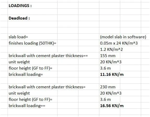
- Next go to loadcases and create a new loadcase with the name Deadload.
- Next select deadload option from the drop up box and select dead load.
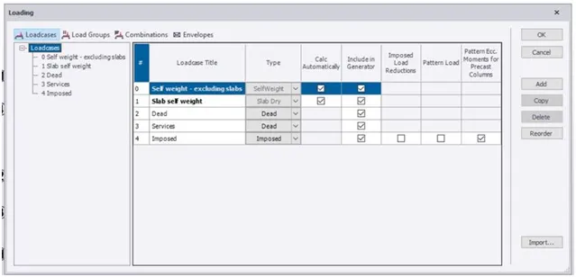
- We have to use the IS standard values for deadload and apply the values calculated in the excel sheet.
- In the left side enter the value of load and select global z directions.
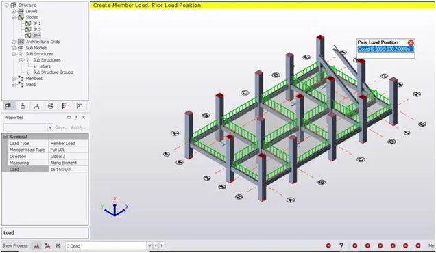
- Now with the help of cursor place the area deadload on the slabs and beams.
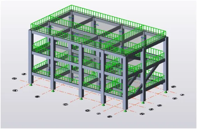
RESULT : Hence, calculation and applying of the dead load to the structure is done successfully.
Q2 ) Calculate live load in design report based on IS code and apply live load on the model.
ANS)
AIM : To calculate live load based on IS code and to apply live load on the model.
TOOLS USED : MS Excel. Loads. Loadcases. Live load. Area load.
PROCEDURE :
- First open MS Excel and do the live load calculations.
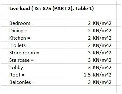
- We can get the values of live load from IS standard codes.
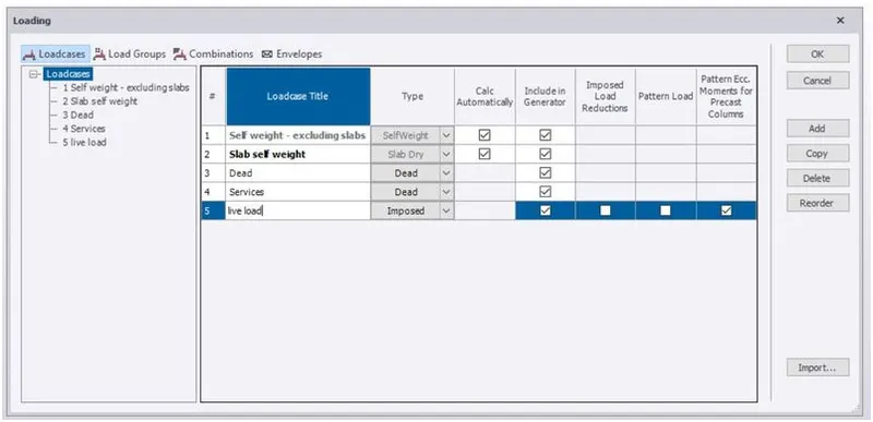
- Go to load cases and add imposed live which is used to apply live load.
- The live load values are different for each and every types of rooms.
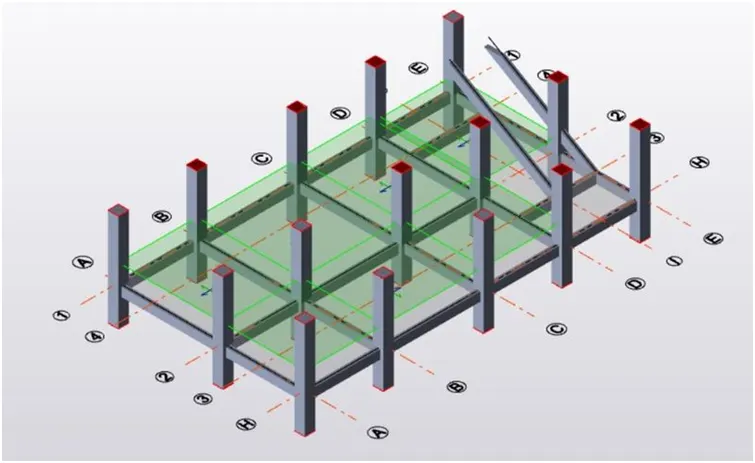
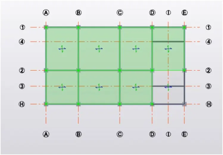
- After selecting live load, use area option to apply the loads on the model in each floor.
- All the live loads will be applied.
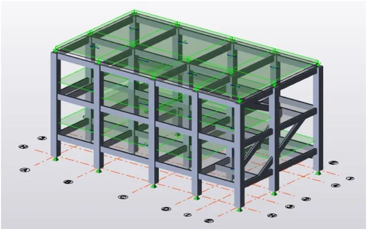
RESULT : Hence applying the live loads to the model is done successfully.
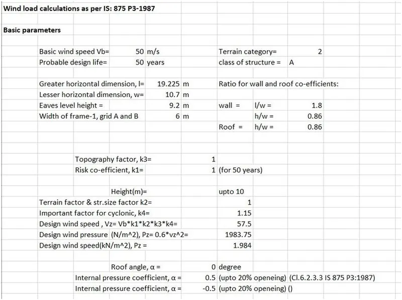
Q3) Generate manual wind loading in the design report based IS code as per the following input
- Basic wind speed = 50m/s
- Terrain category 2
ANS 3)
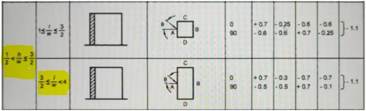
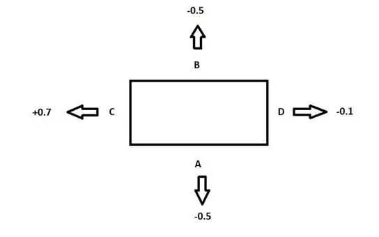
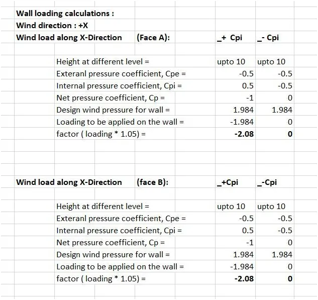
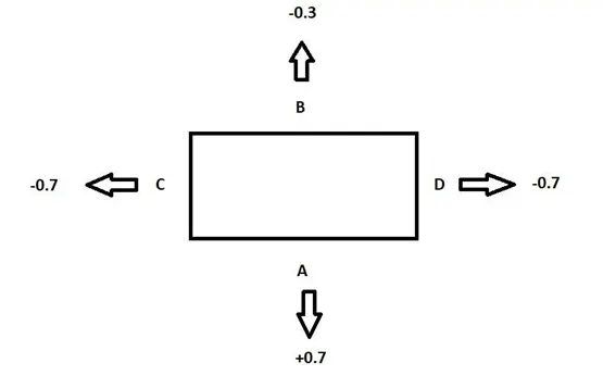
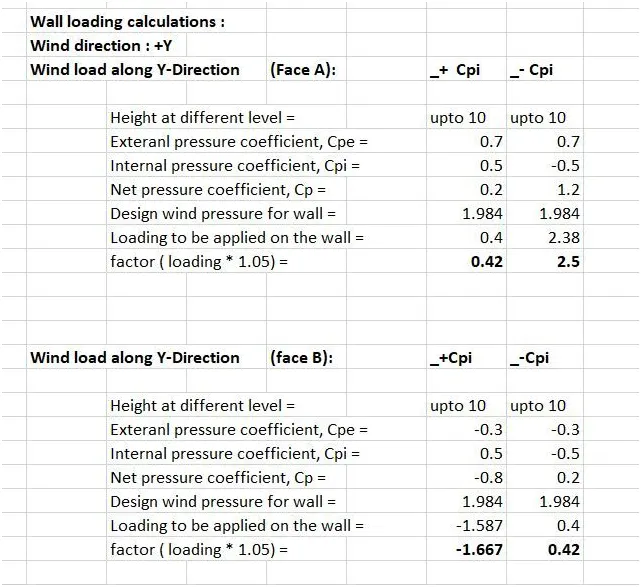
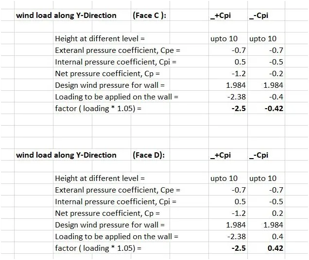
AIM: To generate the wind load calculations.
RESULT :
Q4) Based on the above calculation apply the loadings on the model.
ANS)
AIM : To apply the loads based on the above calculation of question 3.
TOOLS USED : Loads. Loadcases. Wind load. Area load.
PROCEDURE :
- First open the file where we have constructed the model.
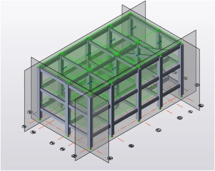
- Next go to loads and select loadcases.
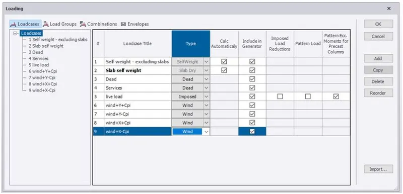
- Create new wind loads for X and Y ( Both +Cpi and -Cpi)
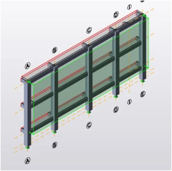
- Select each of the wind loads and apply on the structure.
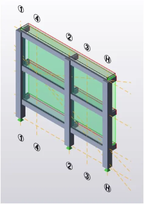
- Before applying loads create wall panels.
- Adjust the coordinate system as
- Face A and B : Global Y.
- Face C and D : Global X.
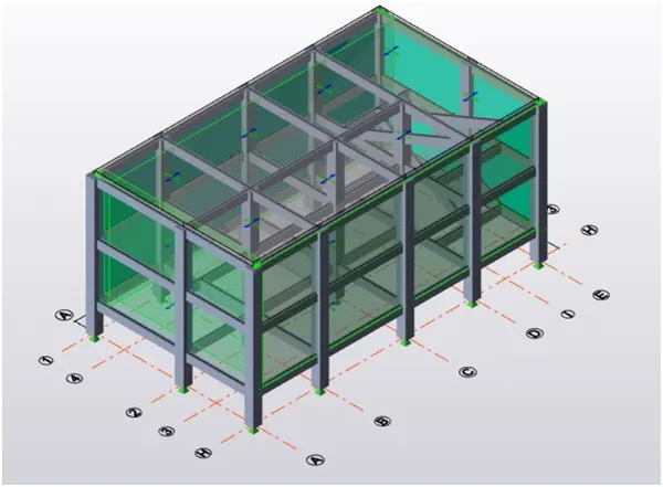
RESULT : Hence, applying the wind loads on the structure using manual calculations is done successfully.