REVIT_3D Rendering of a House plan_Project 1
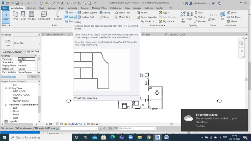
1. AIM: To model a celling for the previously designed project with the help architectural tab above the walls at first floor.
TOOLS REQUIRED : Architecture tab, celling,modify tab. pick line.
PROCEDURE:
- Firstly open the project with the ground floor and first floor.
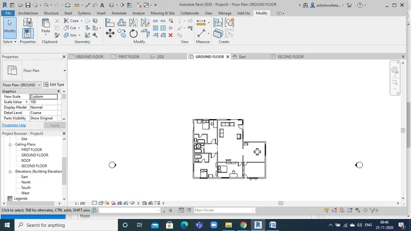
- Now with the help of architectural tab we find the celling option. By clicking on ceiling , click on pick lines to select the desired line for ceiling
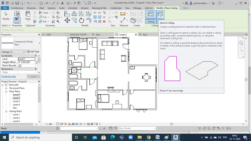
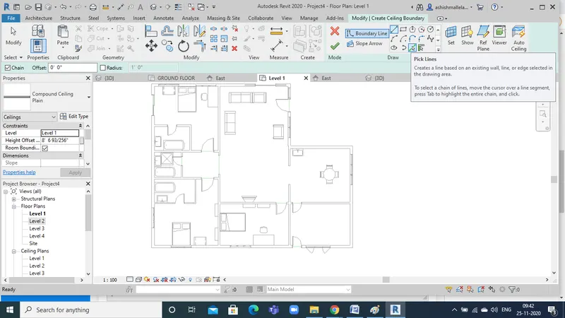
- After picking lines click on finish to get the desired ceiling.
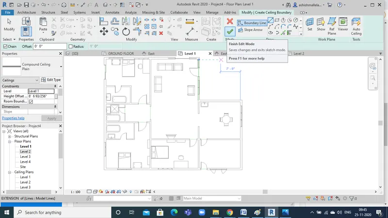
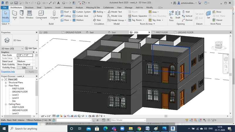
RESULT: Residential building with the celling for the ground and the first floor is successfully completed
2.
AIM: To model a roof on the above designed building and make it 10 degrees sloop roof with the help of adjustment tool bar.
TOOLS REQUIRED: Architecture tool bar , Roof, modify tool bar, pick lines, properties drop down, slop.
PROCEDURE:
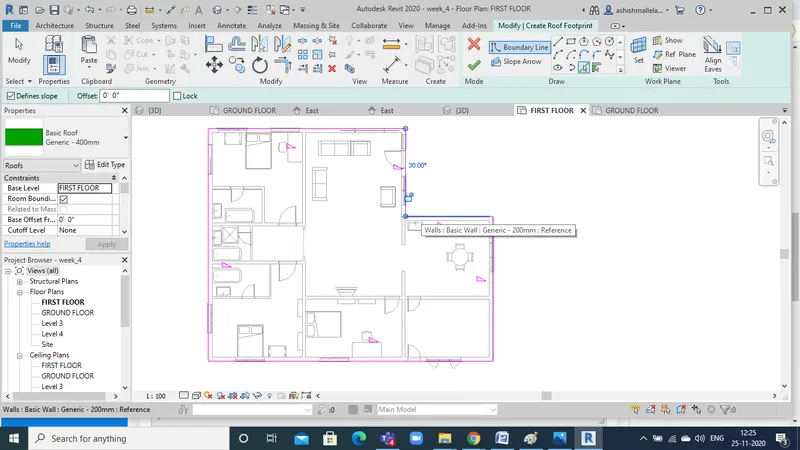
- Firstly we need to open the drawing and now click on the roof option.
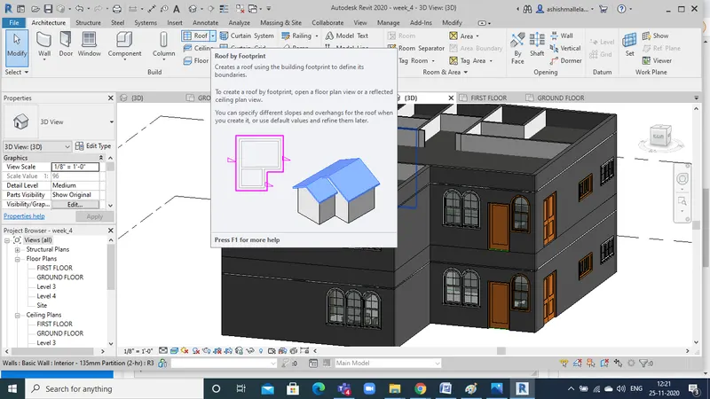
- Click on picklines option in modify tool bar
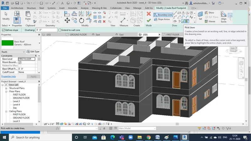
- Now on the drawing we need to select the exterior walls of the the building to place the roof appropriately.
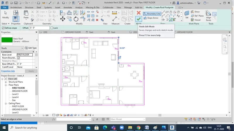
- once we selct finish we can see roof
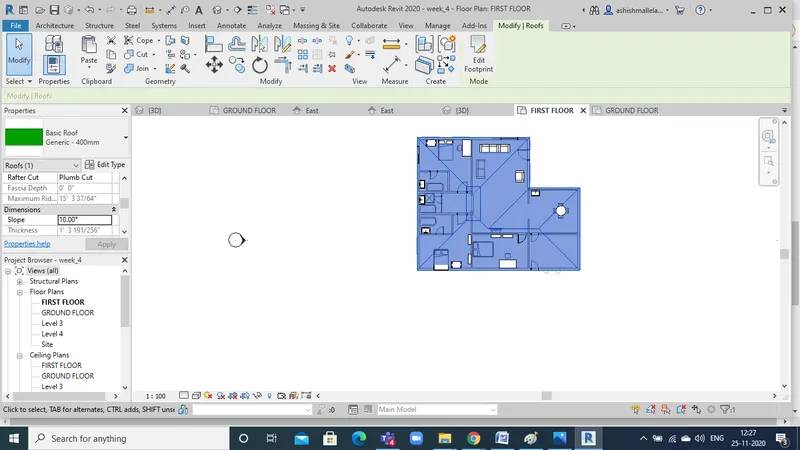
- To make it 10 degrees slope roof we need to the properties and there the settings of the slope by clicking on it .
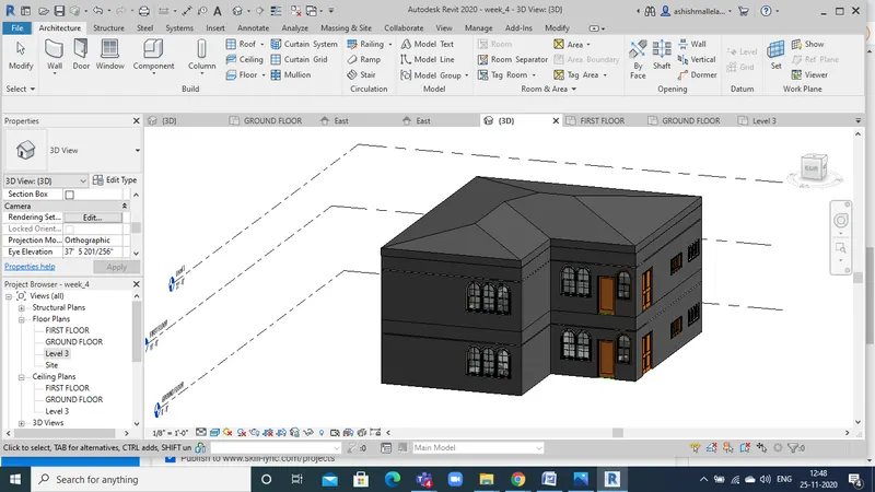
RESULT: 10 degree slope roof is kept successfully.
3.
AIM: To create the plan view of the ground floor and the first floor including the walls,floor and other components
TOOLS USED: Properties browser, floor plans,ground floor, first floor
PROCEDURE:
- Now in the present working project we need to click on the floor plans option in the project browser.
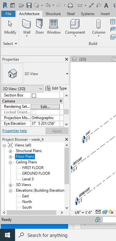
- Now select the desired floor plan that we wanted to show like ground floor plan,first floor etc. in architectural view.
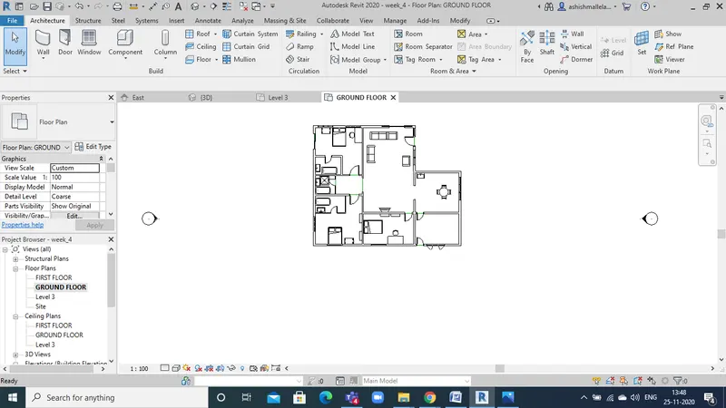
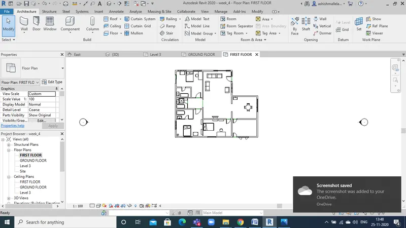
RESULT: Architechtural view of the the floor plan is successfully completed.
4.
AIM: To add dimensions to all the walls and floors with reference to the longitudinal and transverse grids created in the project file.
TOOLS REQUIRED: Architecture tool bar, grids, Annotate,aligned
PROCEDURE:
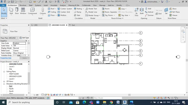
- Firstly select the architectural tool bar and with the help of grids option draw the horizontal and vertical grids.
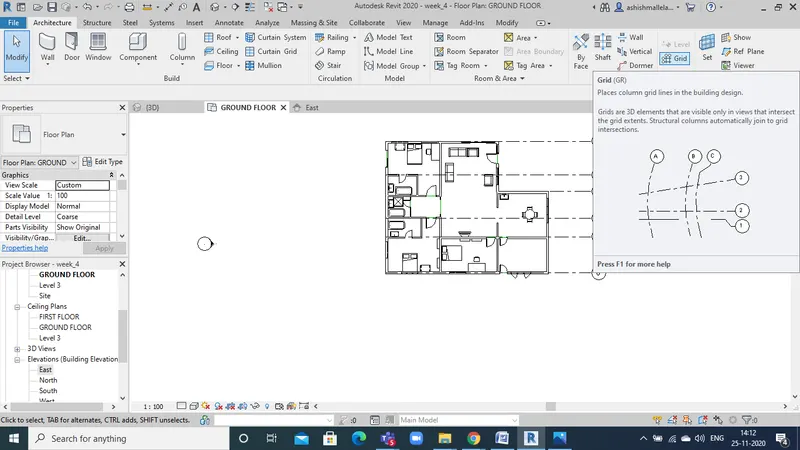
- Now to name the longitudinal girds name them A,B,C and so on from up to down.
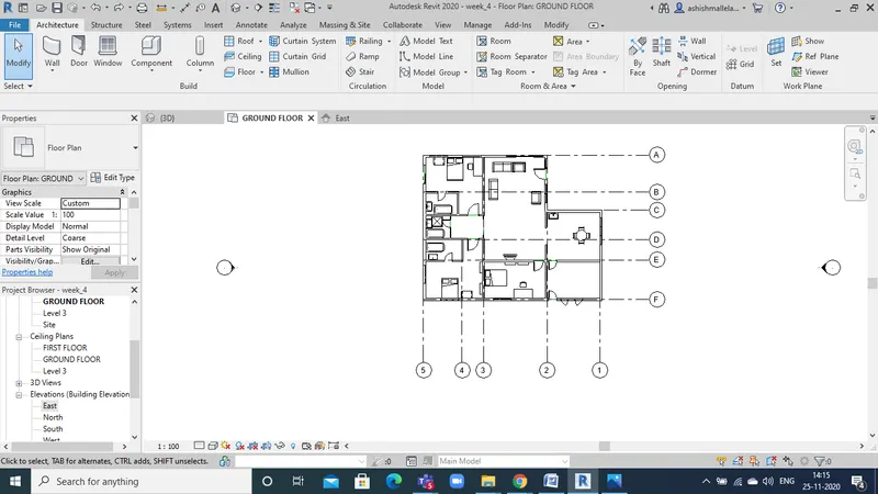
- Now it is the same with the transvere grids nam them as 1,2,3 and so on from left to right.
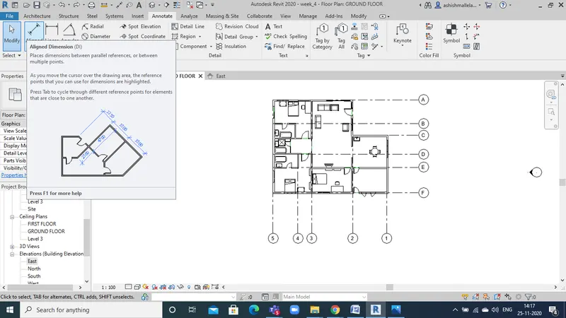
- With the help of aligned tool we can now measure the distance between the walls.
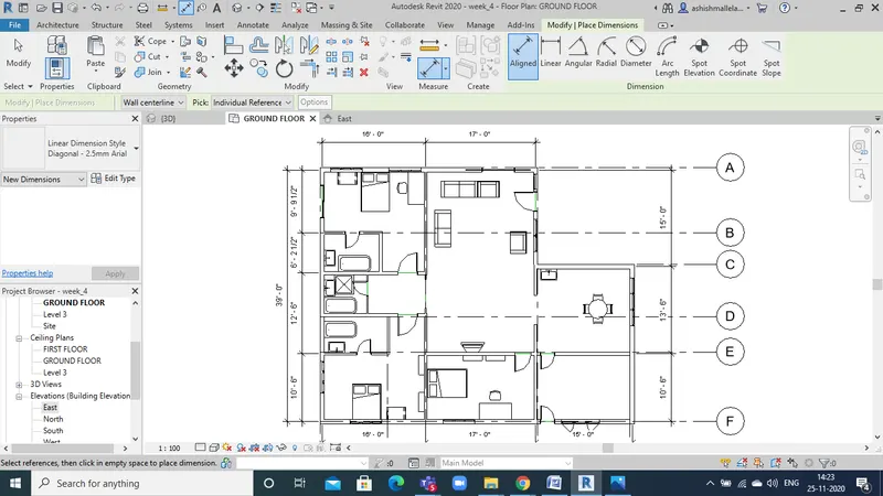
RESULT: Dimensions are included properly in the architectural plan view successfully.
5.
AIM: To create a sheet template from the view tab and afjust the parameters on the sheet to add appropriate views.
TOOLS REQUIRED: View, sheets,project browser, parameters.
PROCEDURE:
- Firstly open the view tab and click on the sheets.
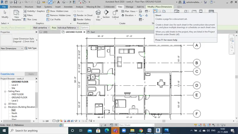
- Now clicking on the a new sheet opens with default naming .
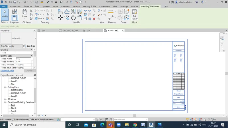
- We can change the names with the help of properties drop down or by just clicking on the particular place itself and change the parameters.
RESULT: sheets are created and named with appropriate parameters successfully.
6.
AIM:TO show the elevation of the building in the north,south,east and west directions.
TOOLS USED: view, elevation, Project browser, Elevation, east,west,north,south.
PROCEDURE:
- Open the previous projcet and click on the view tool bar. click on the elevation option we are directed to the project browser.
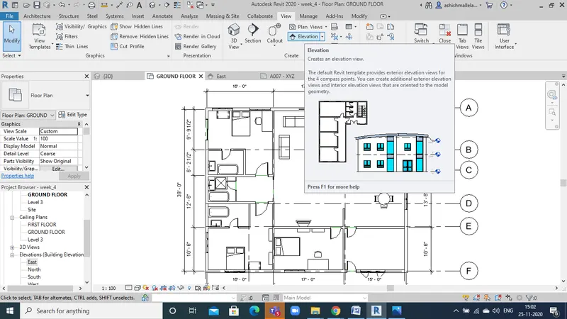
- Now click on elevation and a drop down box appears containing east,west,north,south. Tap on the desired view and get the views
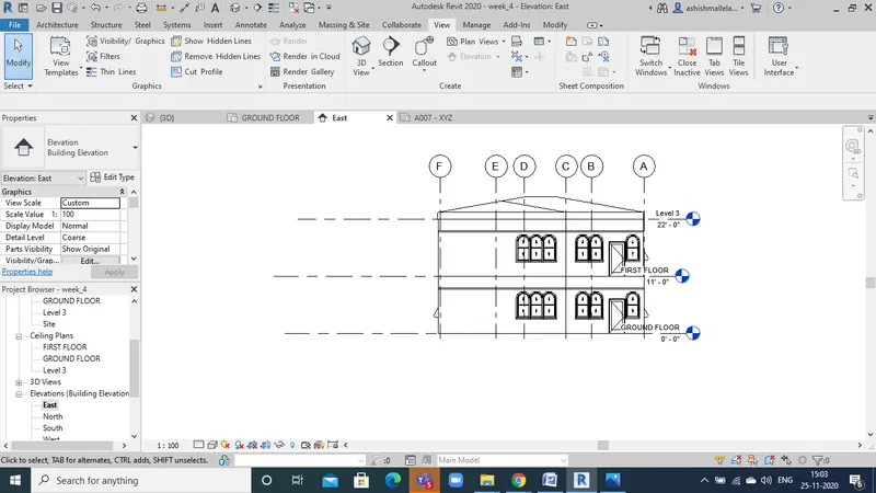
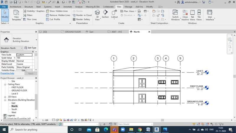
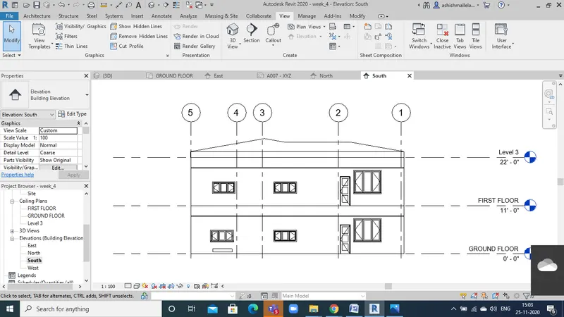
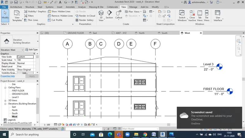
RESULT: We get to see the different views of the project successfully.
7.
AIM: To Produce section cut through each room either cutting across longitudinally or in a transverse direction.
TOOLS REQUIRED: View, section Project browser.
PROCEDURE:
- Open the project,then view tab and select the section tab
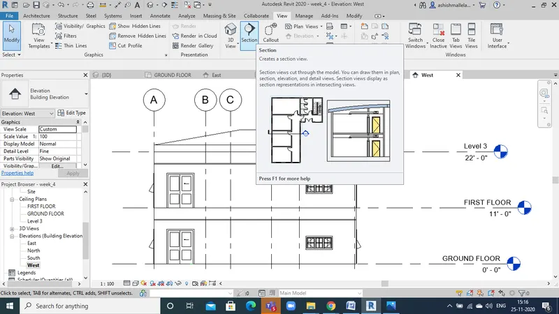
- Now draw the section of your section.
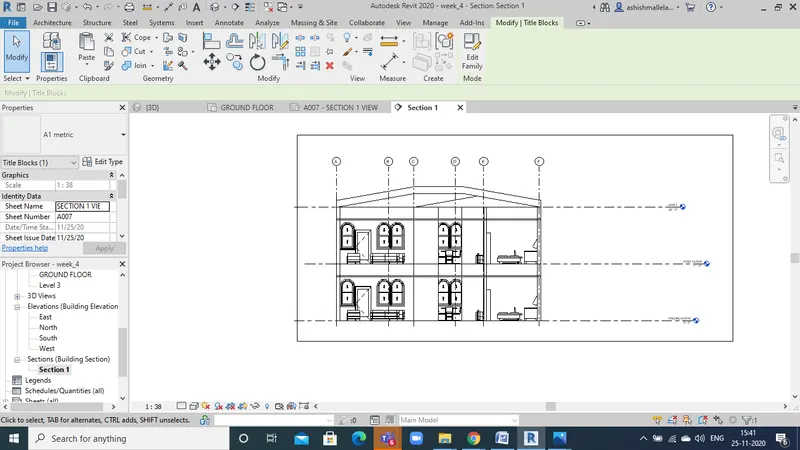
- Draw the line vertically, horizontally if you wanted a longitutinal and transverse section.
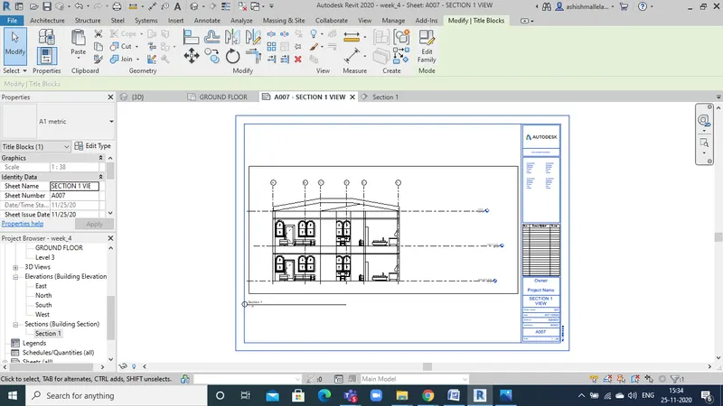
RESULT: section is created successfully.
8.
The different types of plans are plan view, section view, elevation view and they are differentiated as follows
PLAN VIEW: It is the top view of the horizontal cross section of any design.The plan view will establish the layout of the walls, doors, windows, etc.The image of the project lies in the 2-D plane. It is used by designers and architects to produce finish schedules and the majority of the architectural features of a project. The majority of the plans in a construction is in plan view.
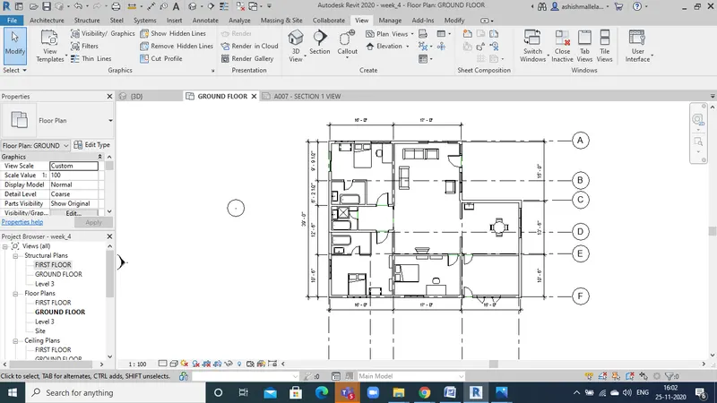
SECTION VIEW:It is the view which is obtained when a project is cut or seen through.It is used to go through the interor of the plan.This help several engineers to communicate and studydeeper into the plans
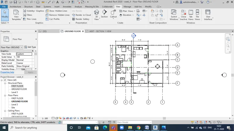
ELEVATION ViEW:It is the front view of the vertical cross section of any design.Elevations are essential for detailed renovations. This view helps to view an object in all 4 directions
9.
AIM: To create the multiple sheets as following.
TOOLS REQUIRED: View, sheets,properties,graphics Insert, image
PROCEDURE:
- Firstly open the view tab and click on the sheets.
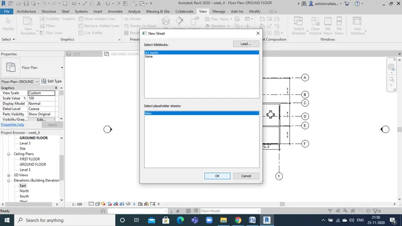
- A new dialog box opens and we need to select the desired type of sheet.and once we clickok we get new sheet.
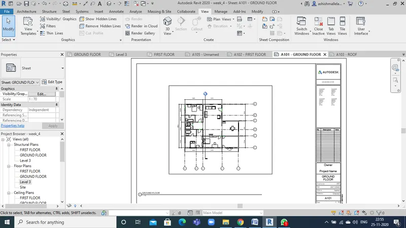
- Now name the sheet as A101 and place the ground floor plan picture there.
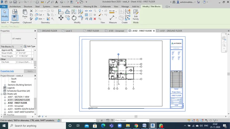
- Name the another sheet as A104 and place the first floor plan there.
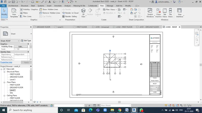
- Name the next sheet as A103 and place the roof plan there.
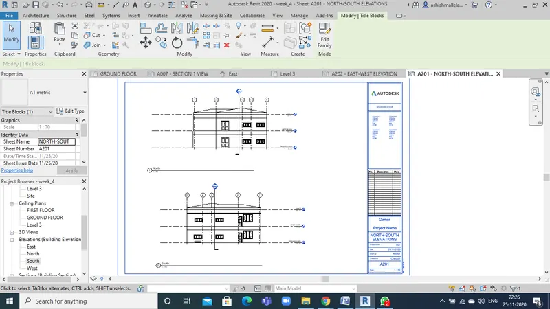
- Name the next sheet as A201 and the place the North South elevation plan there.
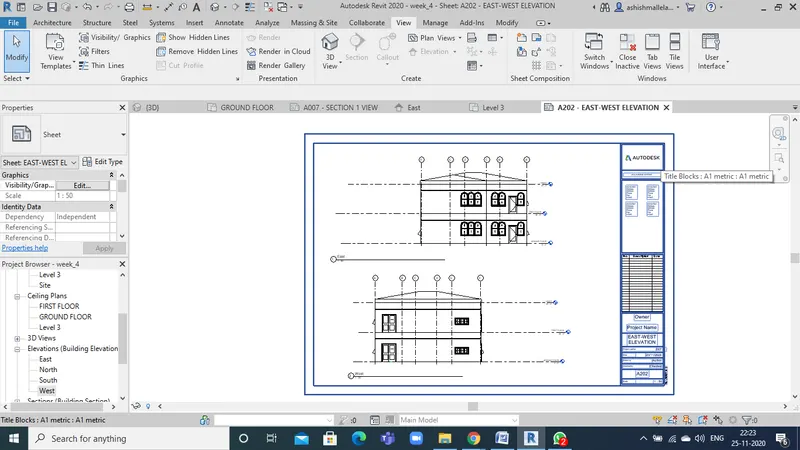
- Name the next sheet as A202 and place the East Wast elevation plan there.
RESULT: The sheets are arranged according to the requiement succesfully.
10.
AIM: To create a 3D camera view of each room and place them in different sheets and name the appropriately.
TOOLS REQUIRED: view, 3D view, camera , sheets, properties, drop down, graphics
PROCEDURE:
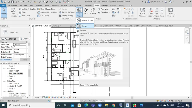
- select the 3D camera view option in the view tool bar.
- Now place the camere so that maximum area of the room is covered to have maximum coverage.
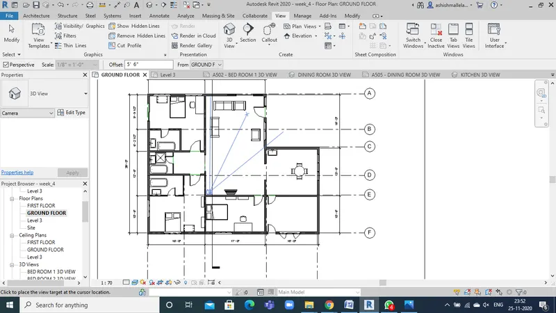
- To get the room picture even more accurately extend the lines at the corner to have the prefect view.
- Select the sheet option and change the parametres accordingly
- Place the desired room 3D camera view of the project in the sheets and name them accordingly.
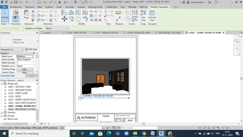
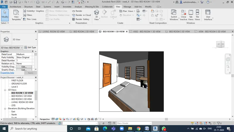
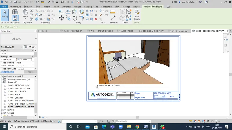
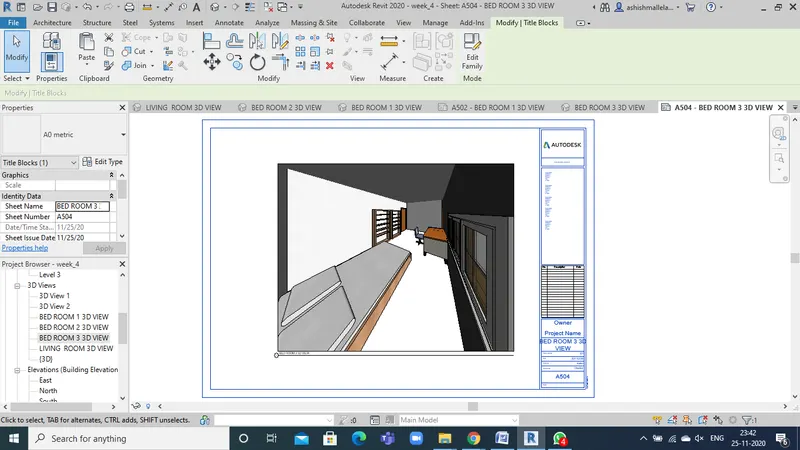
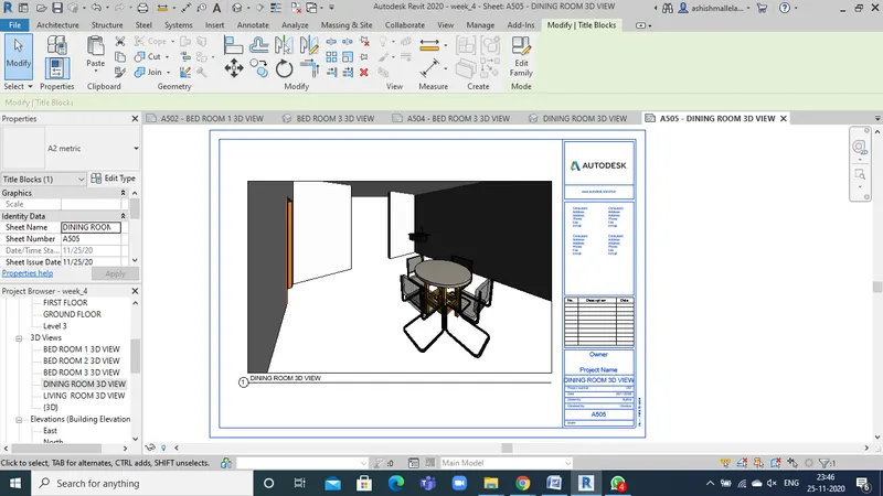
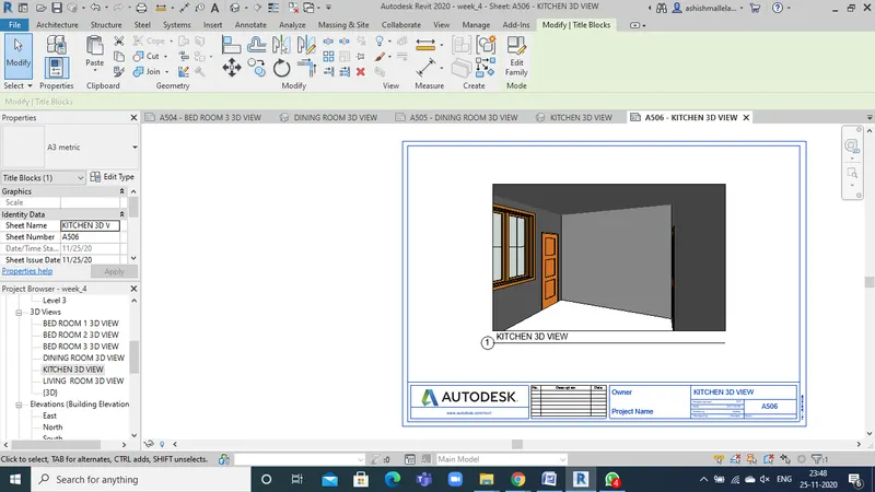
RESULT: Seperate sheets are created and named in a organised way succesfully.