Week 3 Challenge
1.
Aim: To add floor option , set the thickness and to draw the grids for the ground plan.
Tools used :
- Architecture,Floor,Levels,Grids,Material,Thickness,Property browser
Procedure :
- Once you open the previous drawing we did in the 2nd challenge . change the walls according to the requirement if necessary .
- From the architecture option click the floor tool .
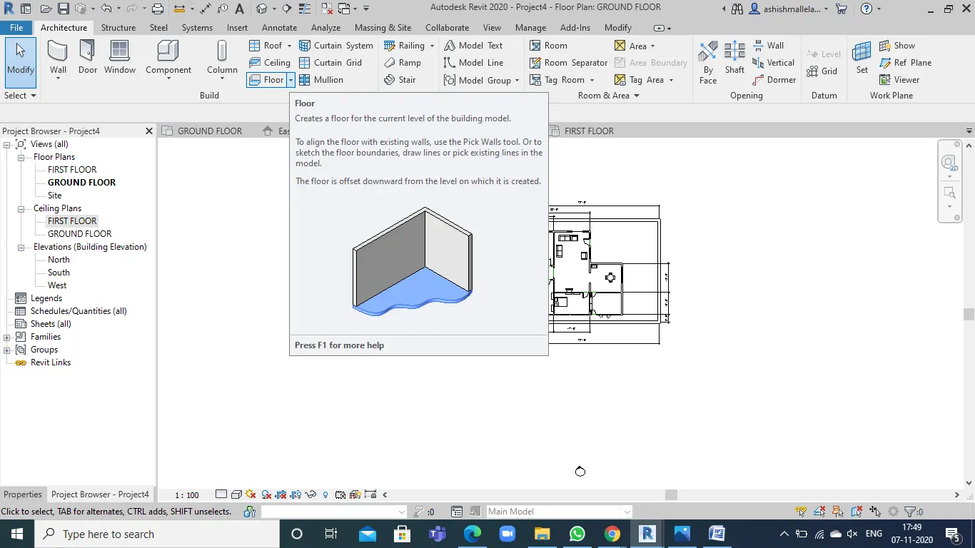
- Once you click the floor tool , modify floor tool option is available.
- Click on the boundary line to select the boundaries of the layout.
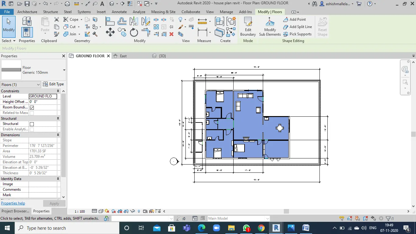
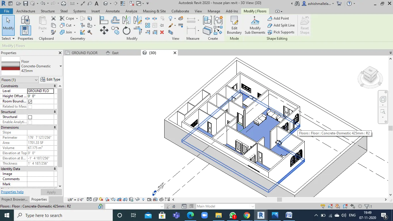
- After selecting the boundaries, select the floor type you wish to add, and change the floor type.
- As per the question given, one should add grid to the layout .
- Horizontal grid lines to be named as a,b,c,d,e,..
- Vertical grid lines to be named as 1,2,3,4,5,6…
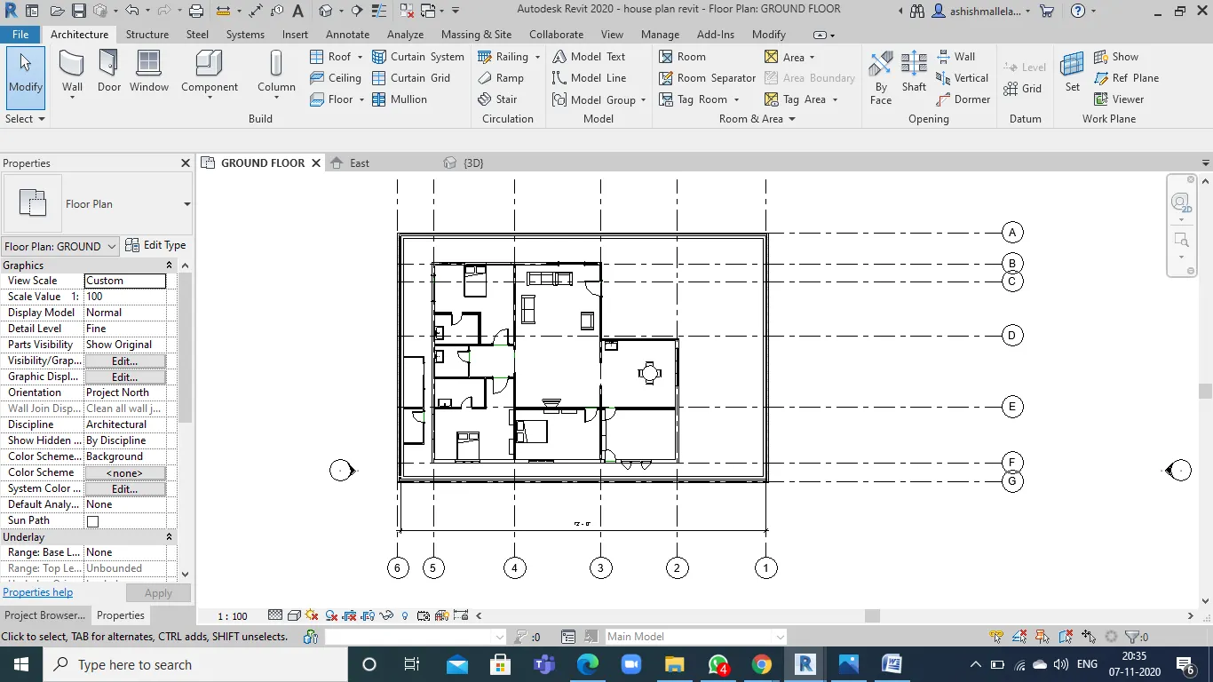
Result: with following the above steps we can draw floor plan for the previously drawn layout and draw grid lines for the ground plan.
2.
Aim: to add walls, modify the boundaries, and to select appropriate thickness and material for walls and floor.
Tools required : Level,View,Default 3D,Edit type,Property browser,Thickness,Structure,Duplicate.
Procedure:
- Once you select the floor in the ground plan view, we have to select the properties and choose edit types.
- Select duplicate and give desired type name
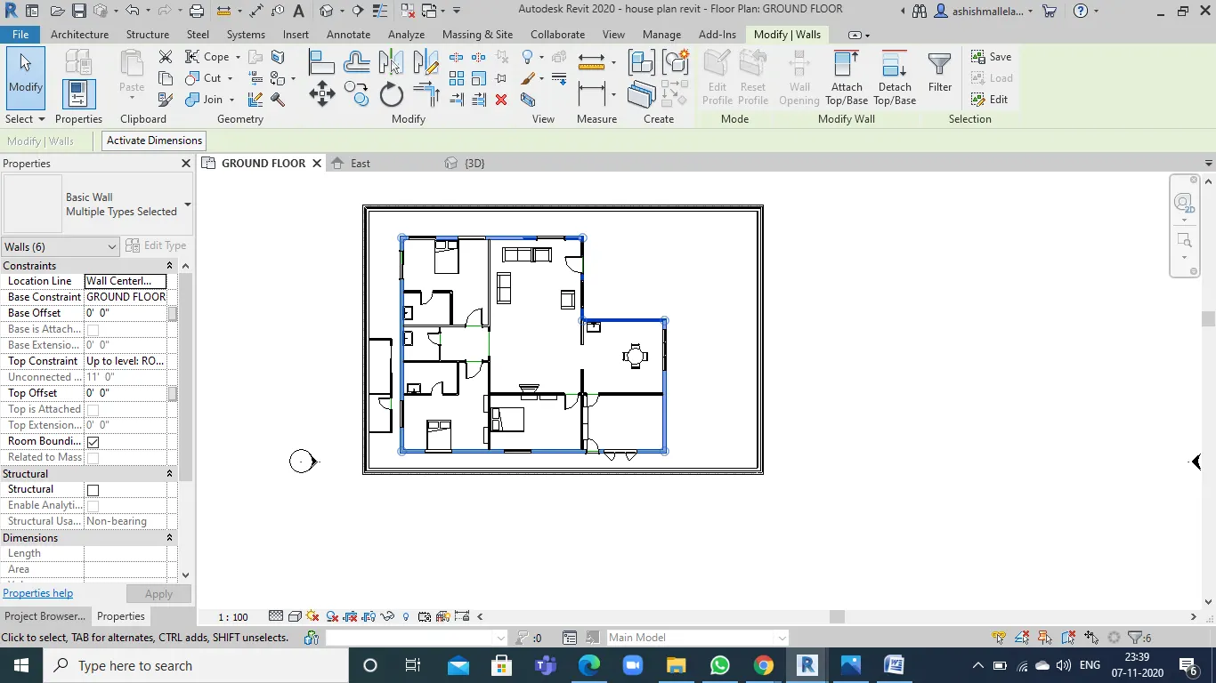
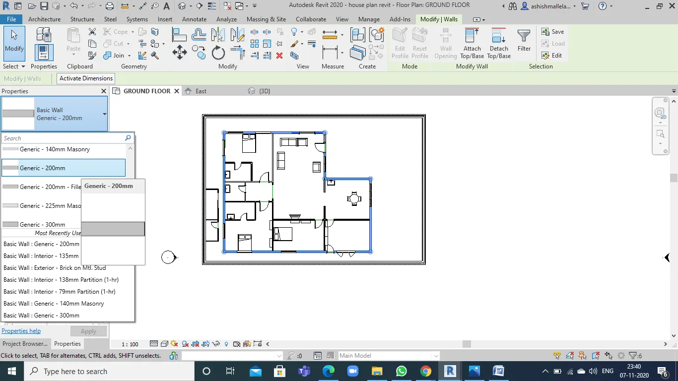
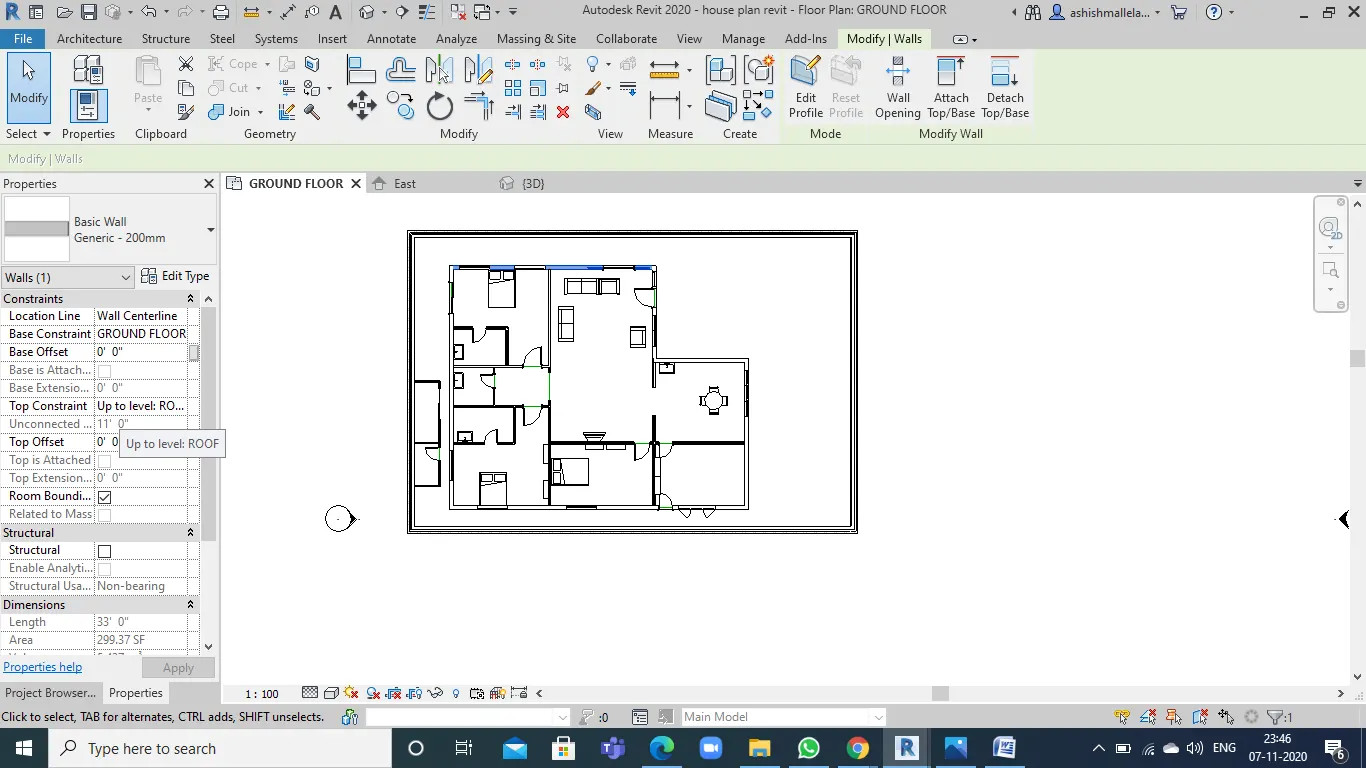
- Once done with the floor, select the wall and give it the desired thickness .
- Repeat the same process for all the walls
Theory :
- From the thing I observed for connecting the walls rather than unconnected “up to level 1st floor “ is beneficial
- For modelling by height option is convenient.
Result: we have successfully modified the walls and floors
3.
Aim: utilize copy and paste options to align elements to a different level.
Tools used : Modify,Copy,Copy from clipboard,Paste,Paste from clipboard
Procedure :
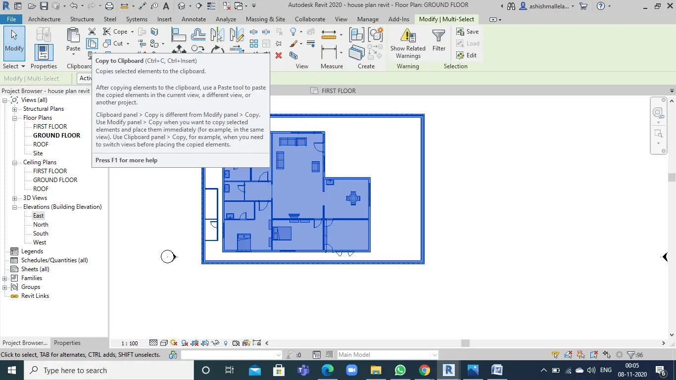
- Once you are done drawing the layout in the ground floor, with the help of mouse select the required part to be copied to the second floor
- After selecting the required things , go to th modify menu and click on copy to clipboard option to copy
- After copying, go to the project browser and paste the copied layout in the secong floor oir level two.
- Then select the 3d view fromview menu and see the two floor view
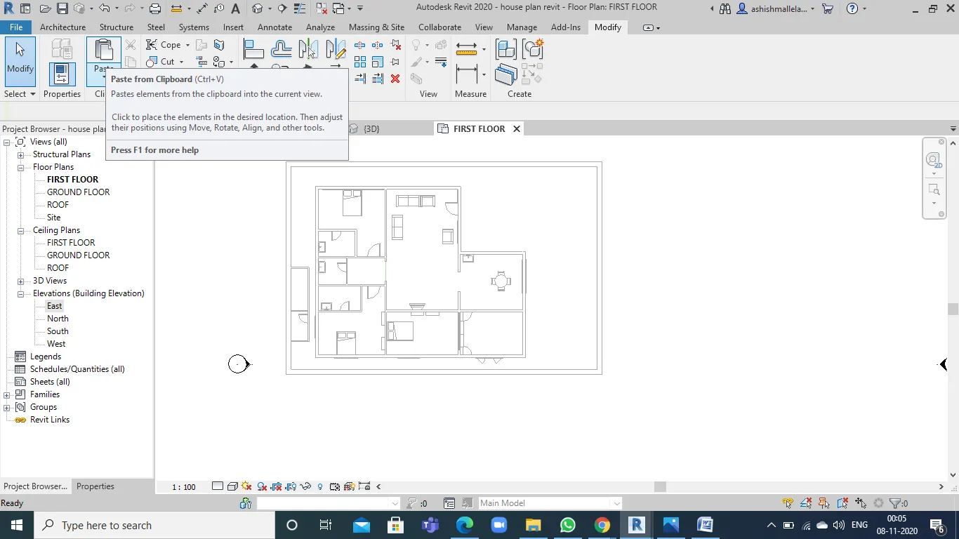
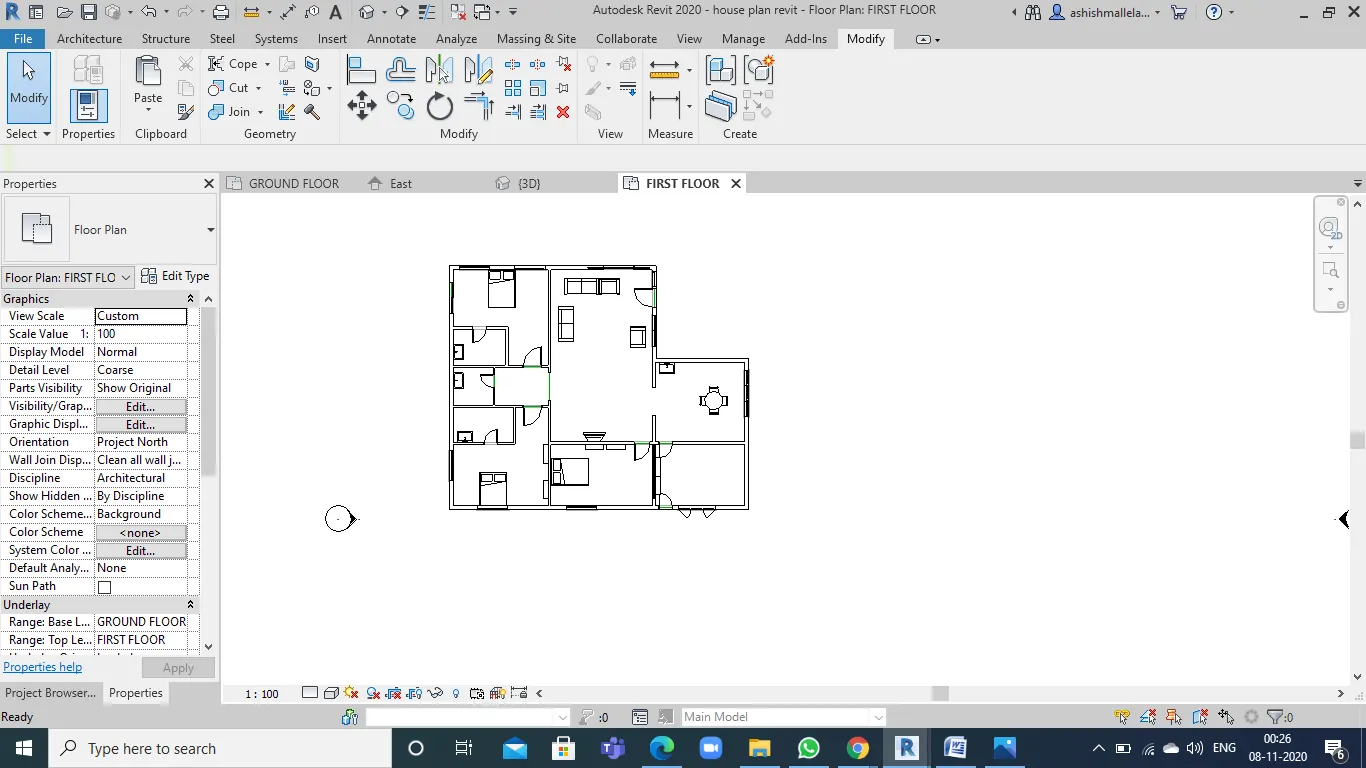
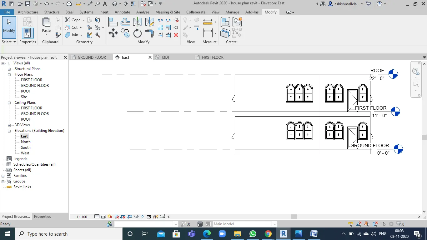
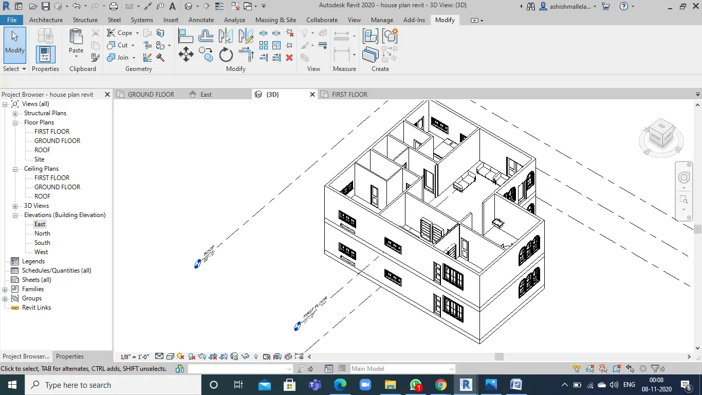
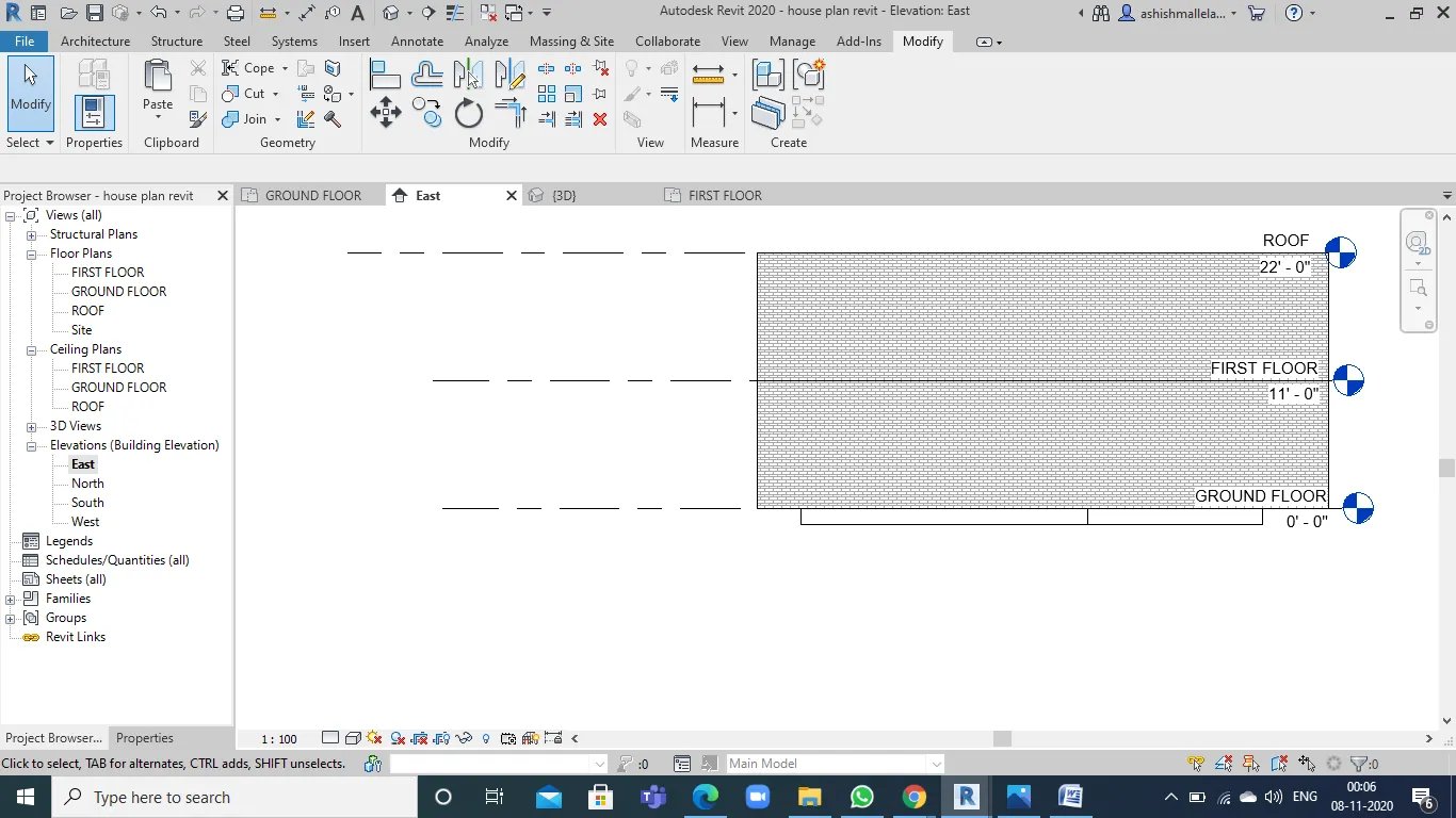
Result : following the above steps , we are able to get the desired result and next floor is successfully completed.
4.
Aim: to make a layout of a desired residential unit
Tools used : Architecture tab,Walls,Trim
Procedure :
- As we have to draw a residential unit layout, we firstly take the help of wall tool available in the architecture tab.
- With the help of architecture tab we draw the layout of the residential unit.
- After drawing the layout, we draw the inner walls with the wall option available.
- The below are the measurements of the residential unit I have drawn
- Living Room/ Drawing Room ( 15’ X 18’)
b. Dining Room (9’ X 11’)
c. Bed Room ( 9’ X 12’ and 15’ X 11’)
d. Rest Room ( 10’ X 12’ )
e. Kitchen (8’ X 10’)
Result: Drawing the layout drawing for the residential unit successfully completed.
5.
Aim: In the layout created, draft the levels of details you would like to include.
Tools used:
- Insert
- Load family
- Architecture
- Windows
- Door
- View
- Default 3Dview
Procedure:
- After completing the layout. With the help of wall tool draw the remaining inner walls
- Click on insert menu and select load family to add components
- Use annotate menu to mark the dimensions
- Then click the view menu and select the 3d view option and look at the view of the project
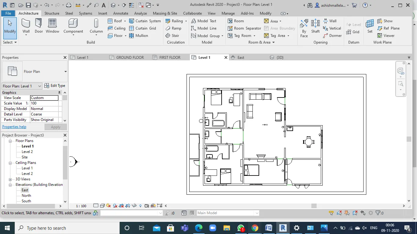
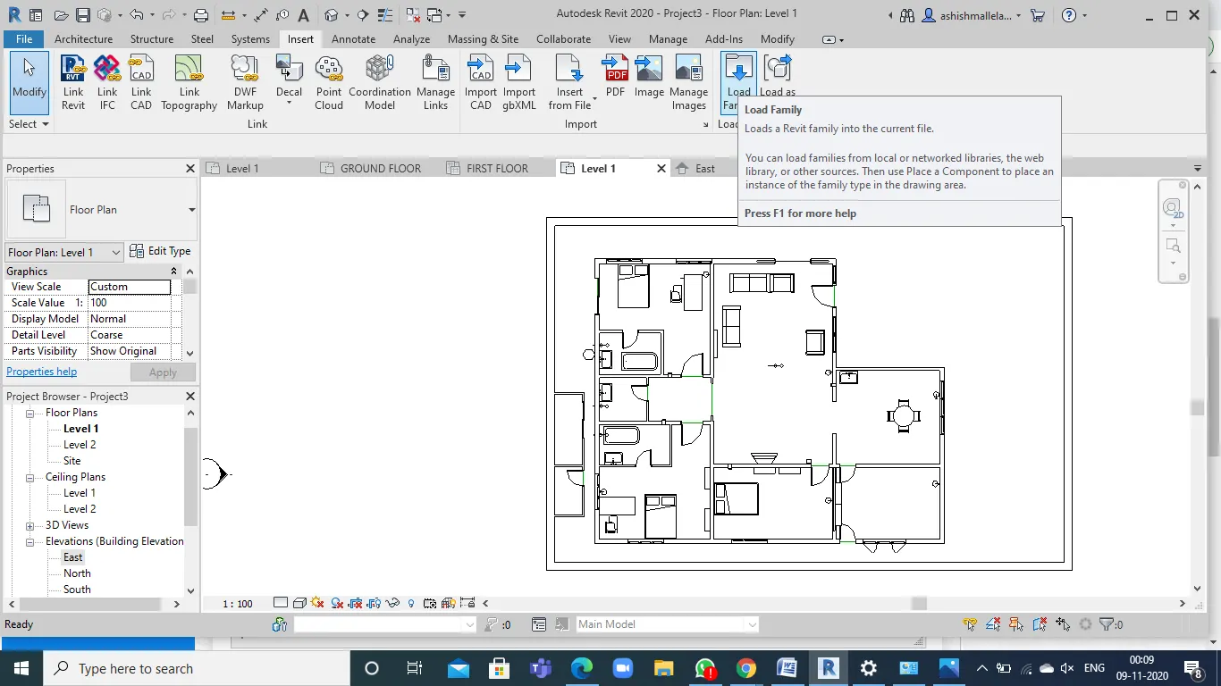
- Result: we have sucessfully placed the compnents in place and got a 3D view.