Week 8 Challenge
- In the Ultracapacitor (UC) model, we will be looking at the equations that define SOC, current and Open Circuit Voltage (OCV).
- These quantities are the important parameters that define the status of the UC while being used for driving.
- Using the basic working principle of UC, we will look at things that influence the OCV, SOC and capacitance.
- A simple OCV measurement effectively defines the State of Charge (SOC).
- The amount of charge is proportional to the current that can flow through the circuit.
- So OCV is sufficient to determine the basic status of the UC.
SIMULINK MODEL:
1. UC SOC Subsystem:
The SOC equation is modelled as
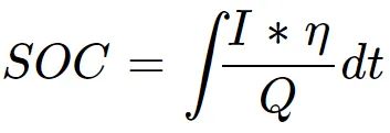
where η = Coulomb efficiency
I = Current
Q = Electric quantity
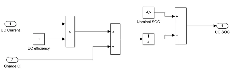
- The current flowing through the circuit when integrated gives the charge flown through the circuit.
- Taking a ratio of it over the total charge capacity gives SOC.
- Q depends on capacitance which is the charge storage capacity measured in Farads.
2. UC Charge Subsystem:
- The OCV is a measure of the electric field between plates.
- The capacitance & OCV is a measures of the electric field between plates.
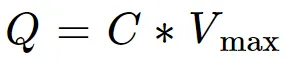
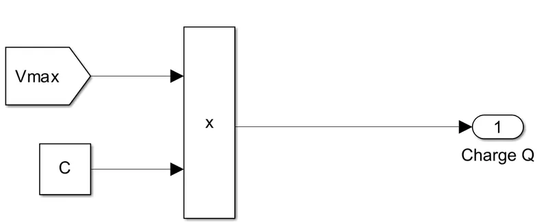
The capacitance & Vmax give Q.
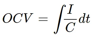
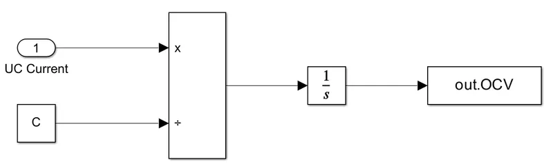
3. UC OCV Subsystem:
The integration of current over C gives OCV.
4. UC Current Subsystem:
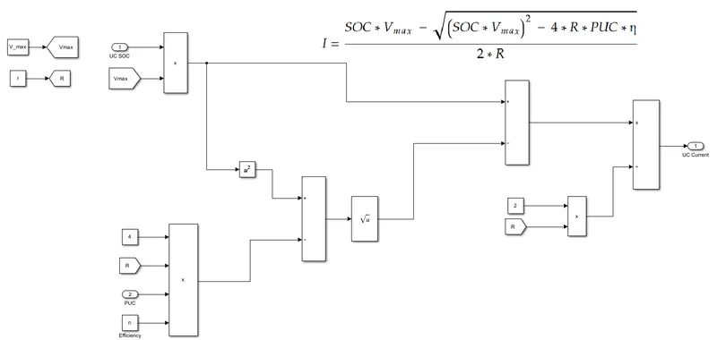
The current consumed is calculated which is fed into a SOC calculation block.

where R = Lumped Resistance
Vmax = Maximum voltage
η = Efficiency during the charge-discharge cycle
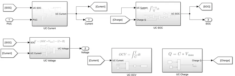
5. UC Model:
In the UC model, calculations for current and SOC are done.
RESULT:
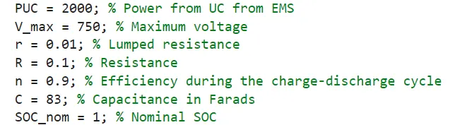
- Certain parameters should be considered for selecting the UC that would be part of the ESS.
- Maximum Charged Voltage should be decided based on DC-DC used.
- The minimum voltage should be decided based on bus voltage and DC-DC.
- The Power or Current required to be delivered by the UC to attain the vehicle characteristics.
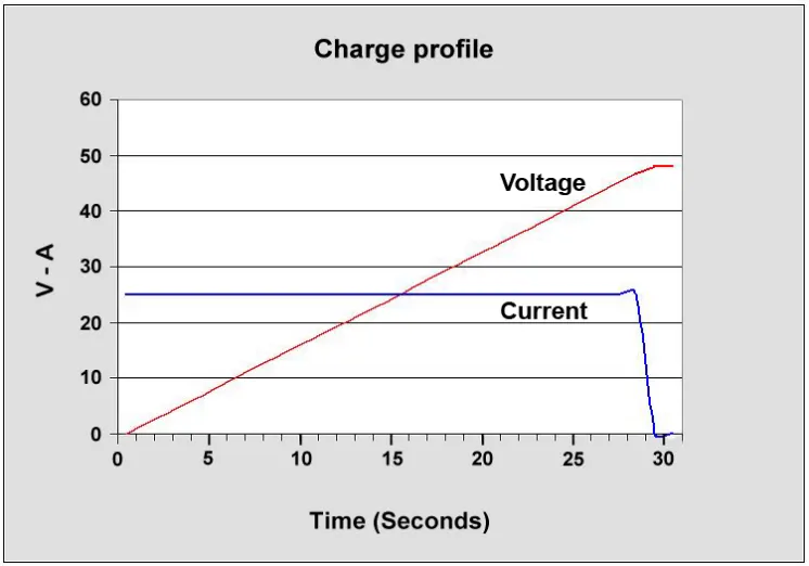
- The voltage of a UC increases linearly when charged and currently drops.
- However, exceeding the voltage of UC beyond a limit can damage the UC.
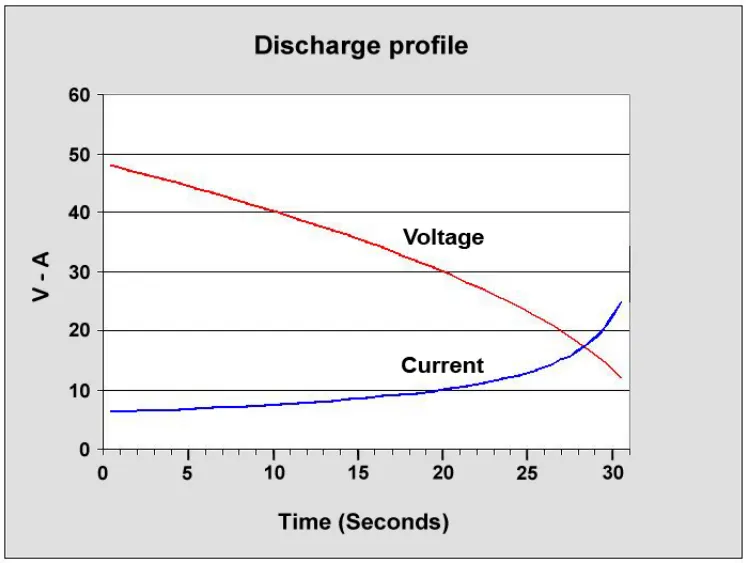
- When discharging the voltage can drop quickly.
- If it gets too low, the DC-DC might not be able to boost it to the bus voltage level.
- The minimum voltage of UC should be kept in mind when the current is drawn.
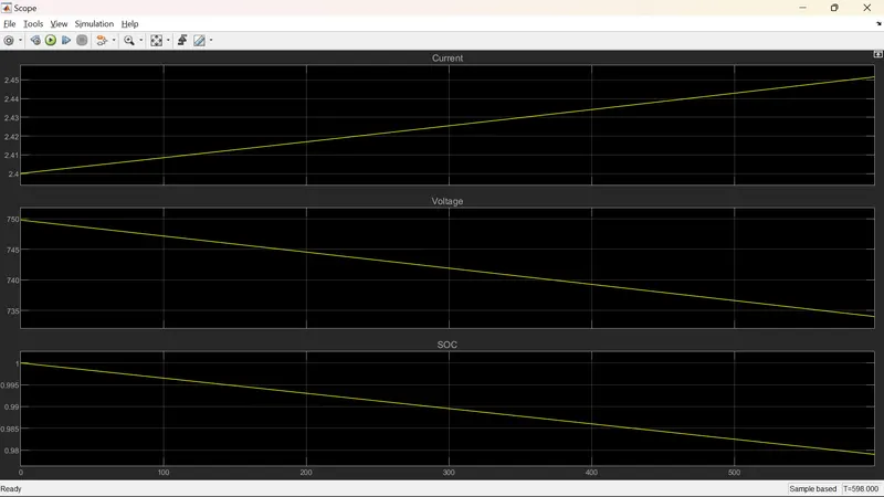
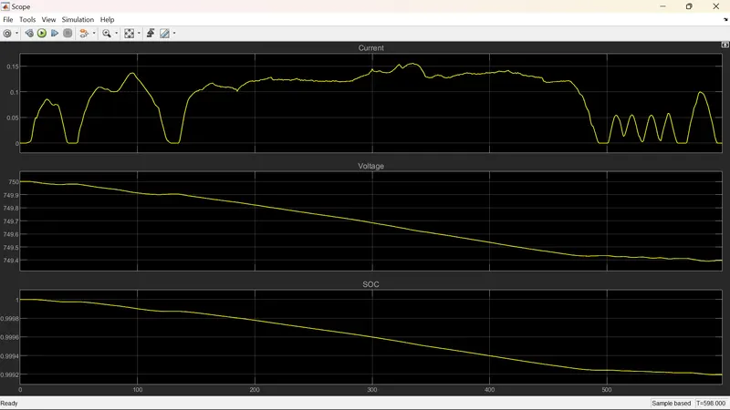
The outputs of the UC Model are as follows:
For Constant PUC = 2000 W
For different PUCs
CONCLUSION:
The UC parameter file is loaded. The Ultracapacitor model is completed and simulated for t = 598 sec.