Week 8 Challenge
Loading, Analysis and Design Procedure in STAAD Pro
1. Applying Load Exercise
For the structure modelled in previous exercise. Apply following loads
- Form a Load case as DL for Dead Load
- Apply Self weight
- Apply member load of 3 kN/m on the rafter
- Apply member load of 6 kN/m on the secondary beams
- Apply point load of 20 kN at node intersecting inclined member on the top chord.
- Form a Load case as LL for Live Load
- Apply member load of 4 kN/m on the rafter
- Apply member load of 7.5 kN/m on the secondary beams
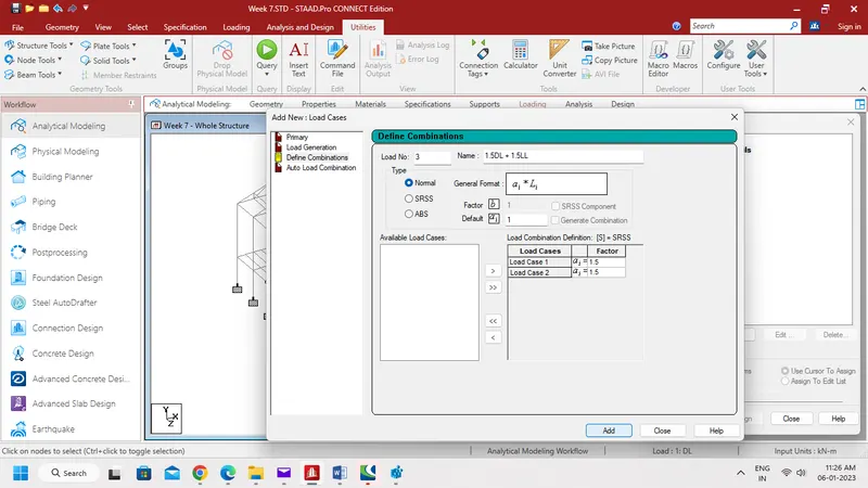
- Form load combination 1.5DL+1.5LL
Aim:-
To apply load cases and load combinations to the model created in Week 7 Challenge.
Procedure:-
Step 1:-
- Open STAAD Pro Connect software and open the STAAD model created previous week.

- Go to Loading tab and select Load Case Details.
- Then click Add, Select Dead load and name it as DL as shown below.
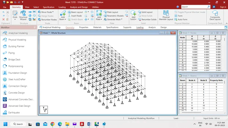
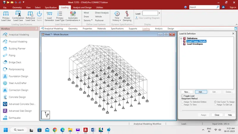
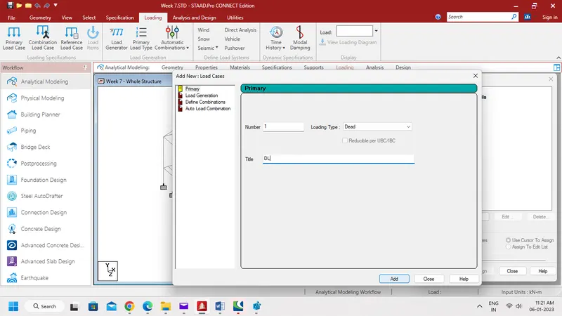
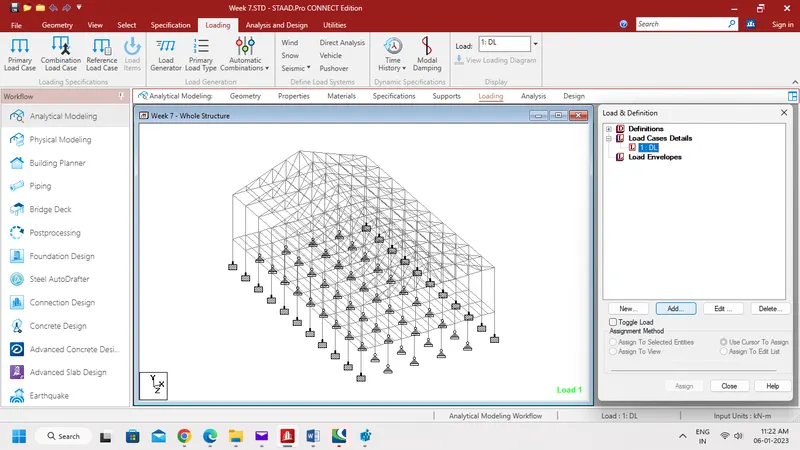
- Now select DL load case, and click Add.
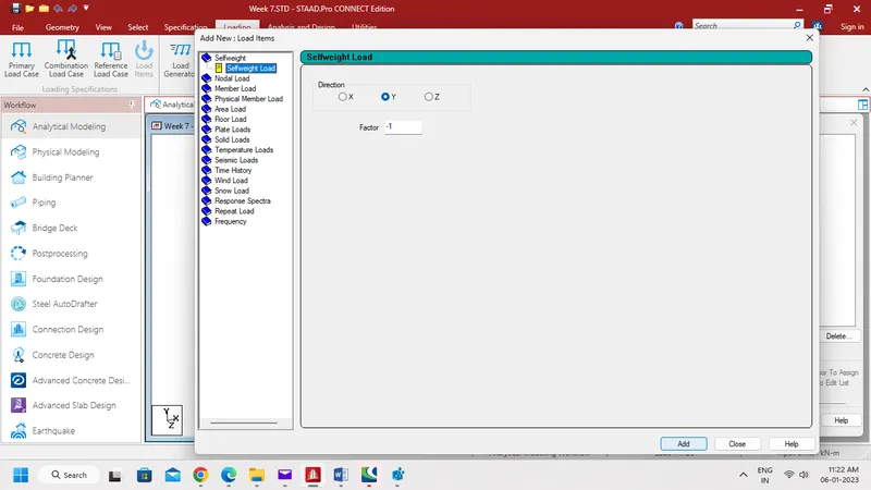
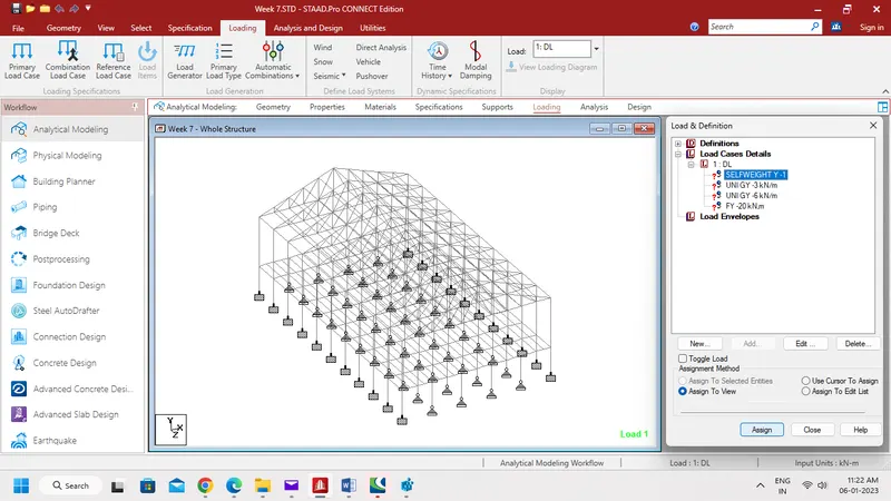
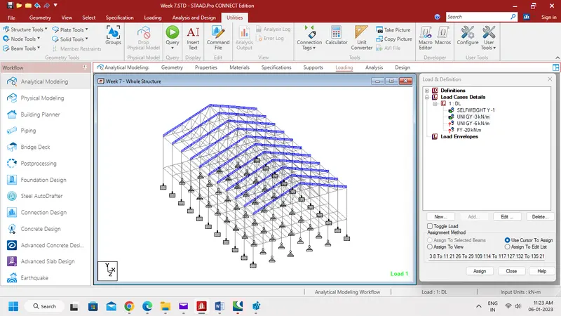
- Then click Selfweight Load and give -1 factor of load at Y direction.
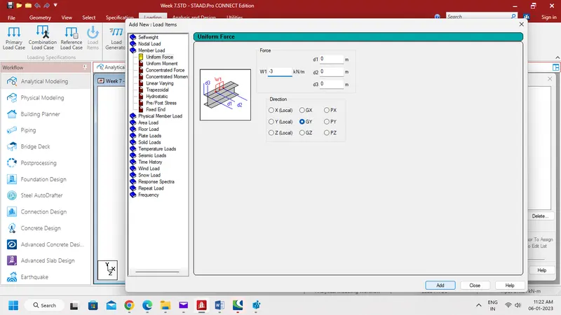
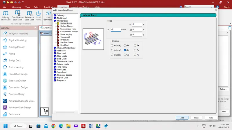
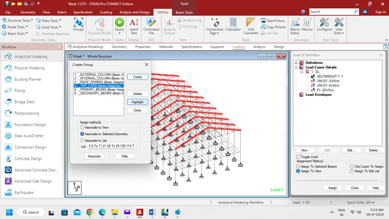
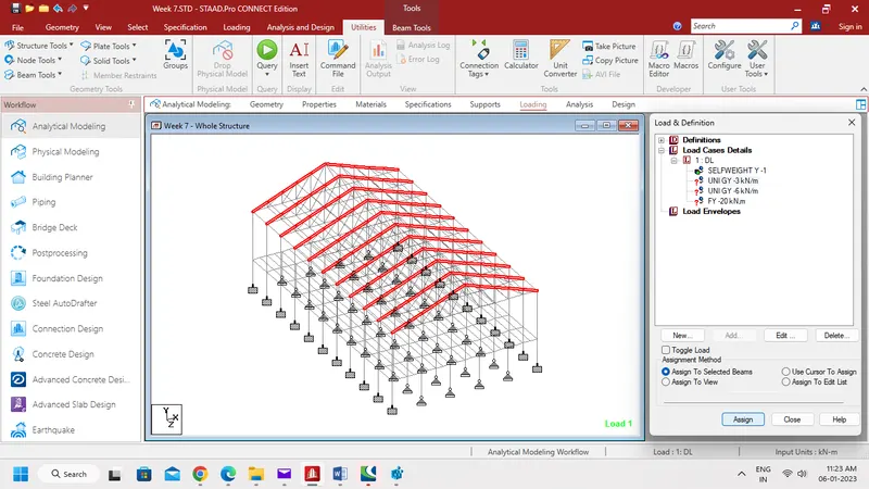
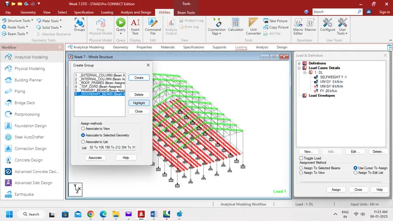
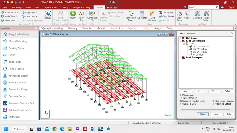
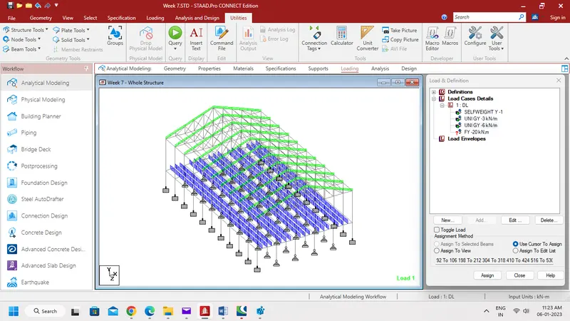
- Now select Member Load, then give input as -3 kN/m for Rafter and -6 kN/m for Secondary beams along GY direction.
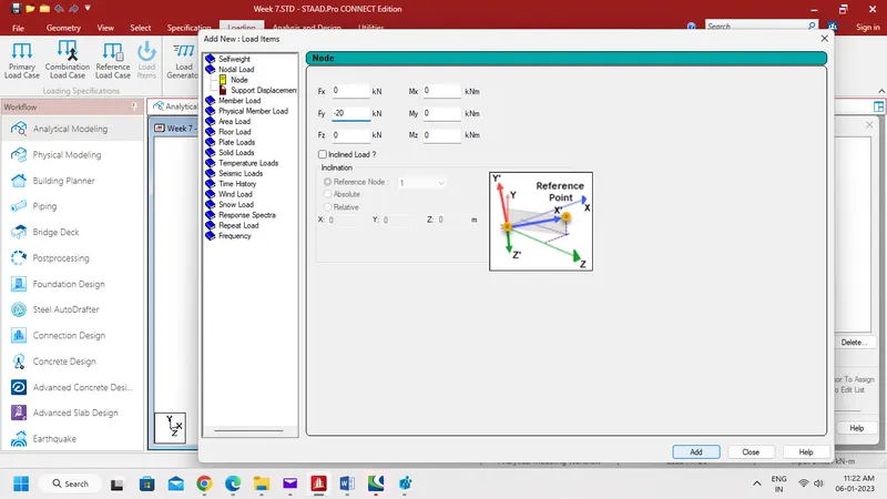
- Then select Nodal Load, give input as -20 kN.
Step 2:-
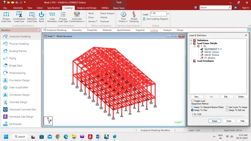
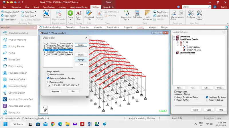
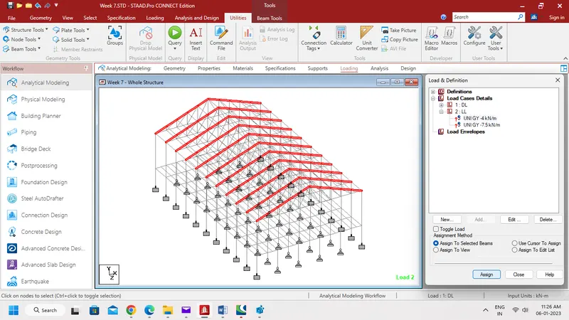
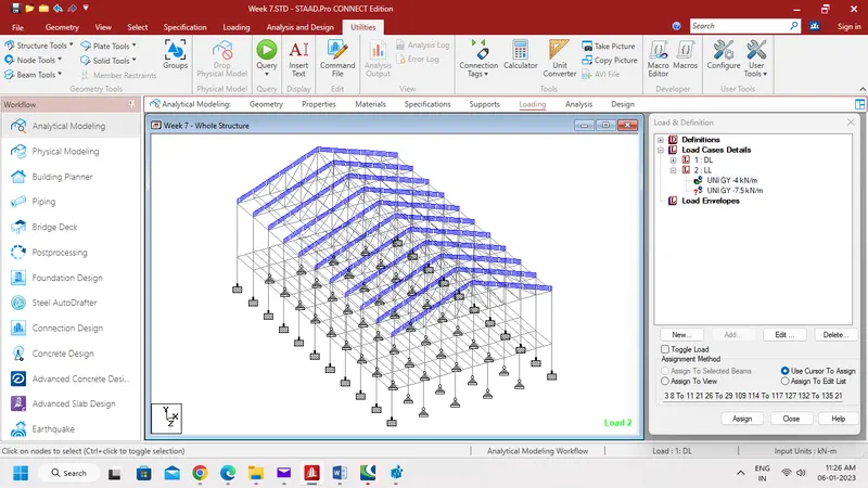
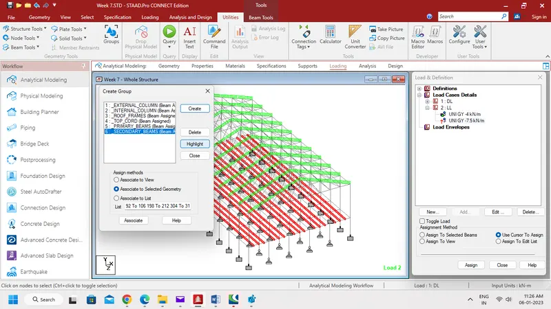
- Assign all Dead Load to the structure as shown below.
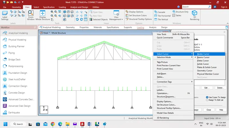
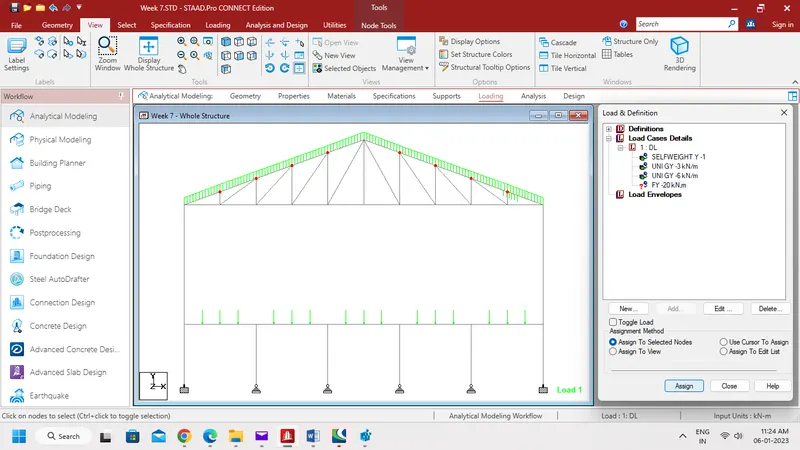
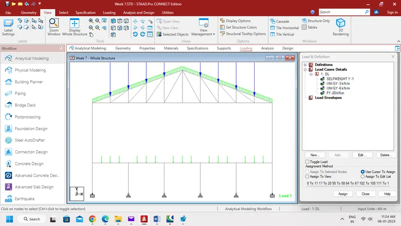
Step 3:-
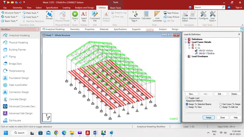
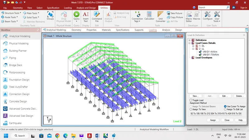
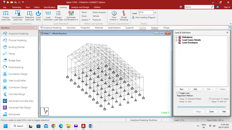
- Again add Load Cases Details as Live Load and name it as LL.
- And add -4 kN/m and -7.5 kN/m of Member Load for Rafter and Secondary beams respectively.
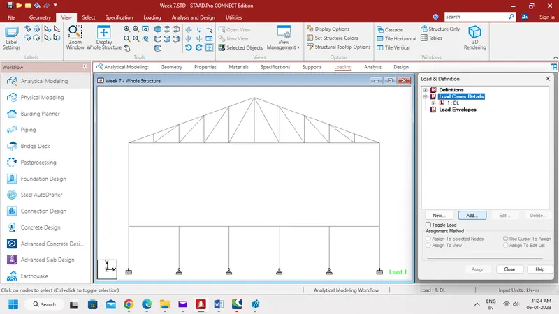
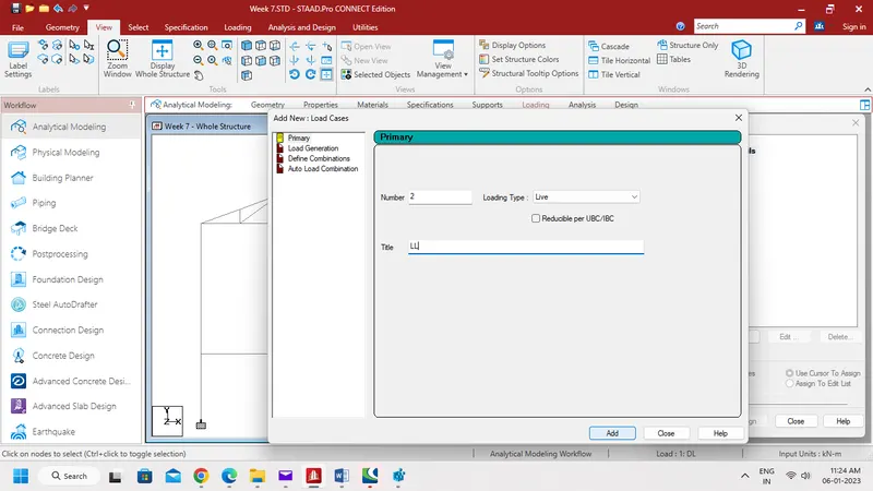
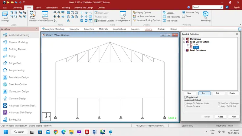
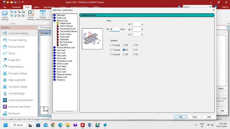
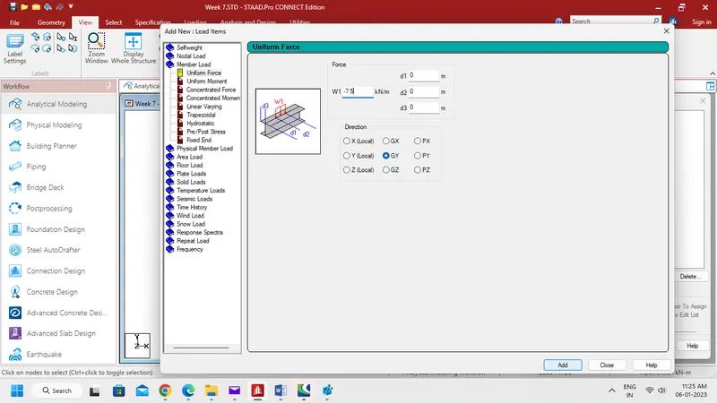
- Now assign the Live load cases to the members as shown below.
Step 4:-
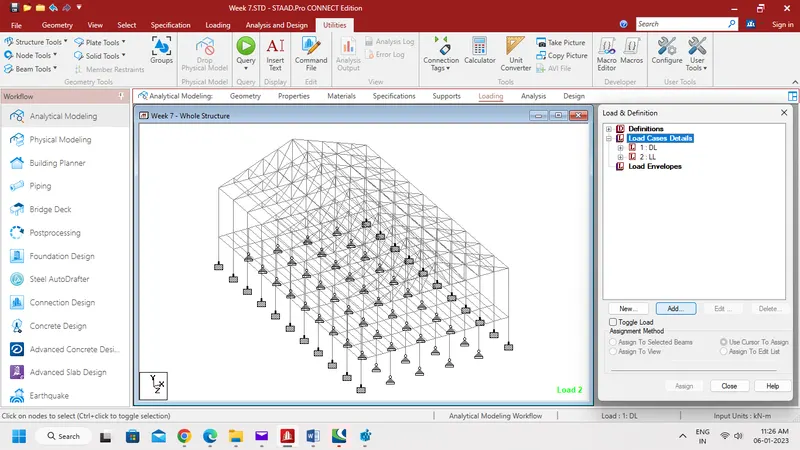
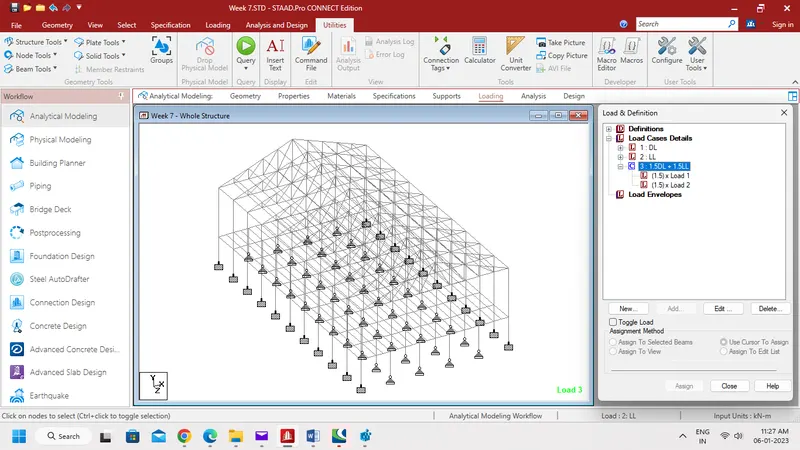
- Then add Load combination as 1.5 DL + 1.5 LL as shown below.
Result:-
The Load cases are defined and assigned the model created in the Week 7 Challenge.
2. Find Maximum Force and Minimum Force for member and present the STAAD result.
Continue previous challenge, Run the analysis and find following results on the member mentioned
- Run the analysis
- Find the Maximum Moment in the Secondary beam for 1.5DL+1.5LL case
- Find the Maximum Axial force on the inclined bracing and identify the member having the maximum force for 1.5DL+1.5LL case
- Identify Bottom chord of Truss having Maximum shear Force & Maximum moment for 1.5DL+1.5LL case and present the values.
Aim:-
To run analysis and find the maximum force and moment of the member.
Procedure:-
Step 1:-
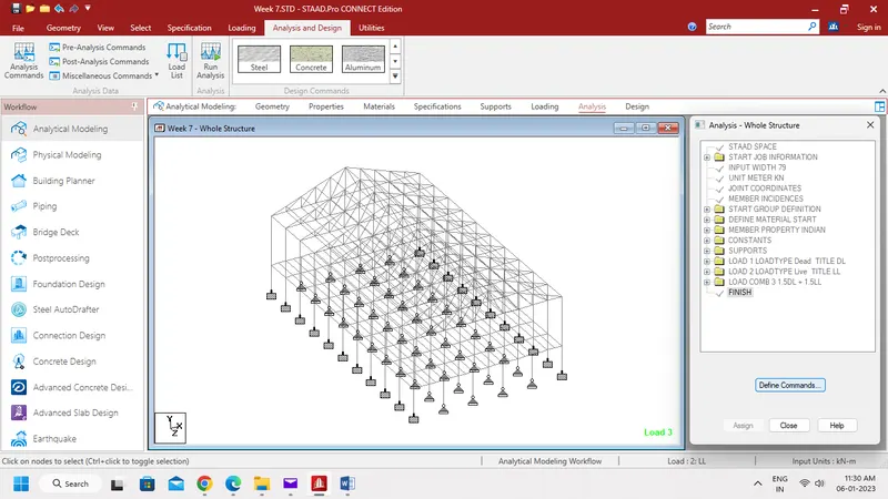
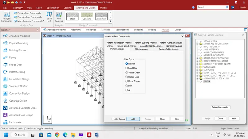
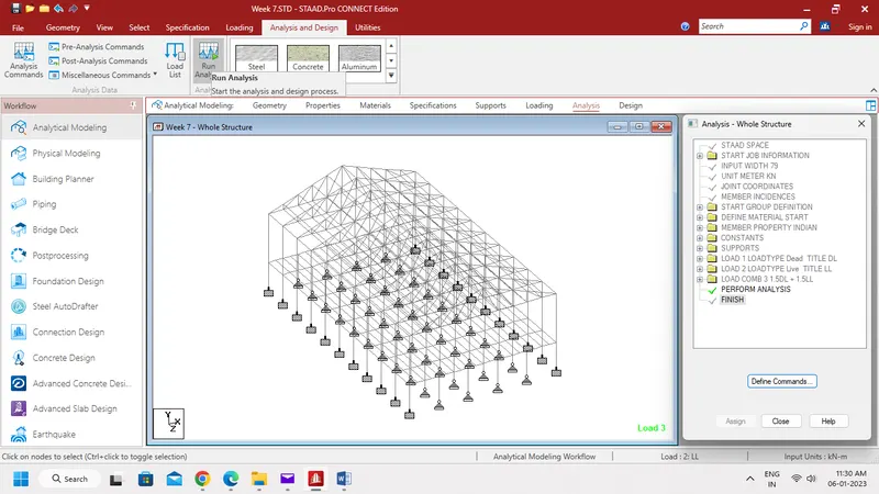
- Go to Analysis Tab, then select Define commands.
- Now define Perform Analysis as shown below.
- Then click Run Analysis.
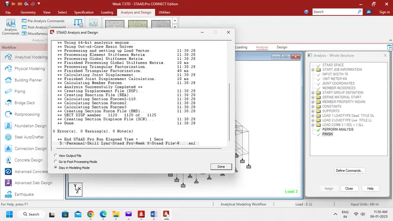
- After Analysis it shows 0 Errors and 0 Warnings.
Step 2:-
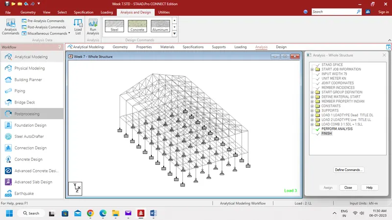
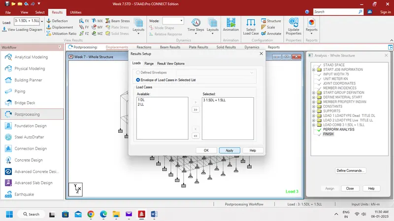
- Now select Postprocessing to see the Results.
- Then choose the Load Combinations.
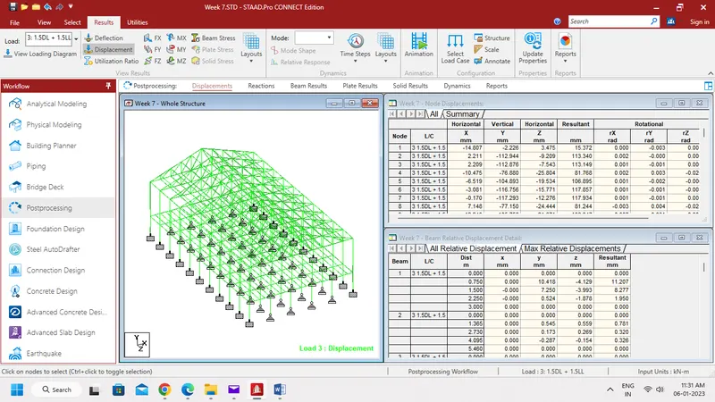
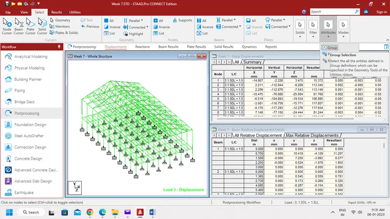
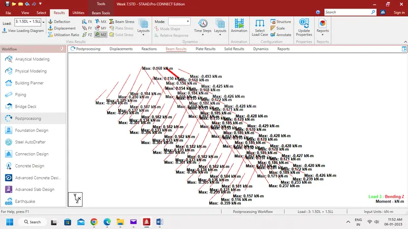
Secondary beam:
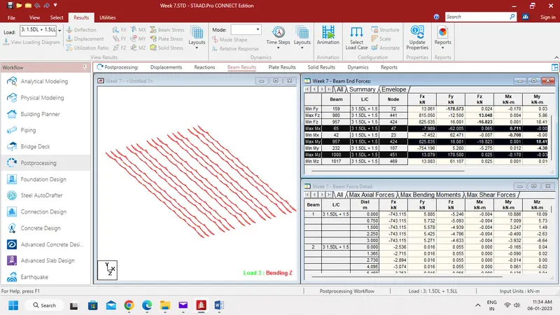
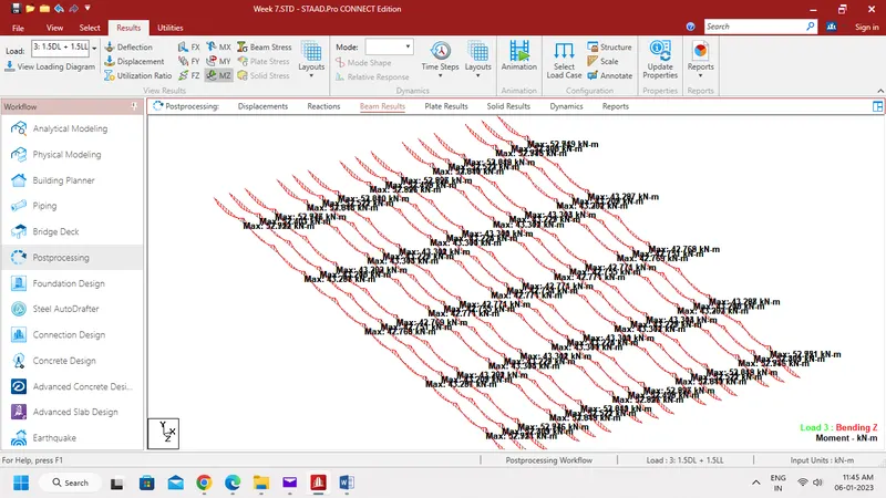
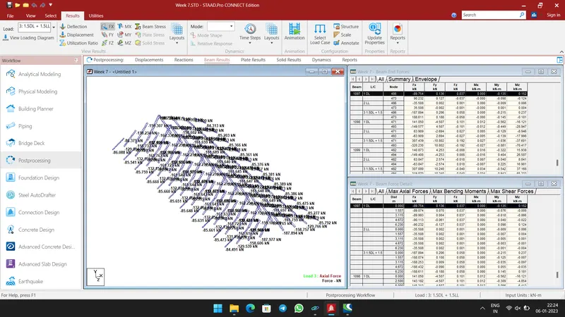
Inclined Bracing:
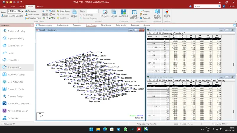
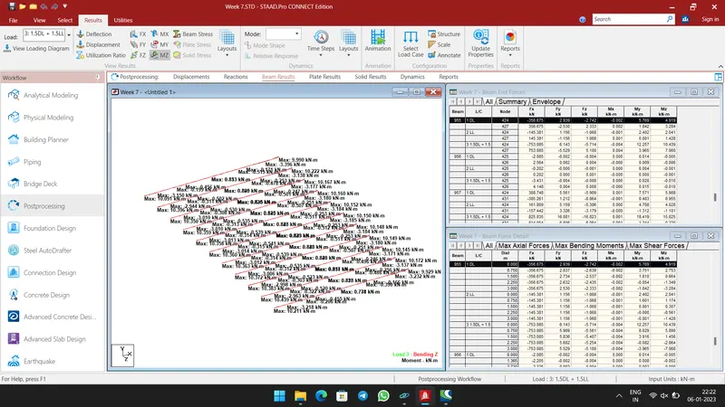
Bottom chord:
Result:-
- The Maximum Moment in the Secondary beam of 15.944 kN-m for 1.5DL+1.5LL case in the beam no is 95, 103, 1049 and 1057.
- The Maximum Axial force on the inclined bracing of 191.760 kN and 191.765 kN for 1.5DL+1.5LL case in the beam no 125 and 991.
- Bottom chord of Truss having Maximum shear Force of 6.143 kN & Maximum moment of 10.439 kN-m for 1.5DL+1.5LL case in the beam no. 955.
3. View and Rectify the Warning, instabilities in the structure
For the attached STAAD file identify the Warnings and fix the same and run the analysis.
Aim:-
To view and rectify the warning, instabilities in the structure attached.
Procedure:-
Step 1:-
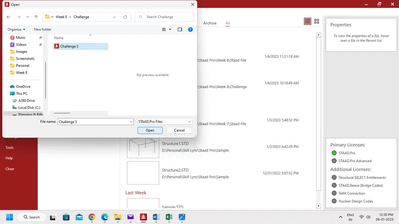
- Open the STAAD File given in the attachment.
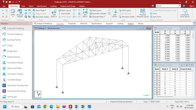
- Then go to Analysis Tab and define Perform Analysis Command.
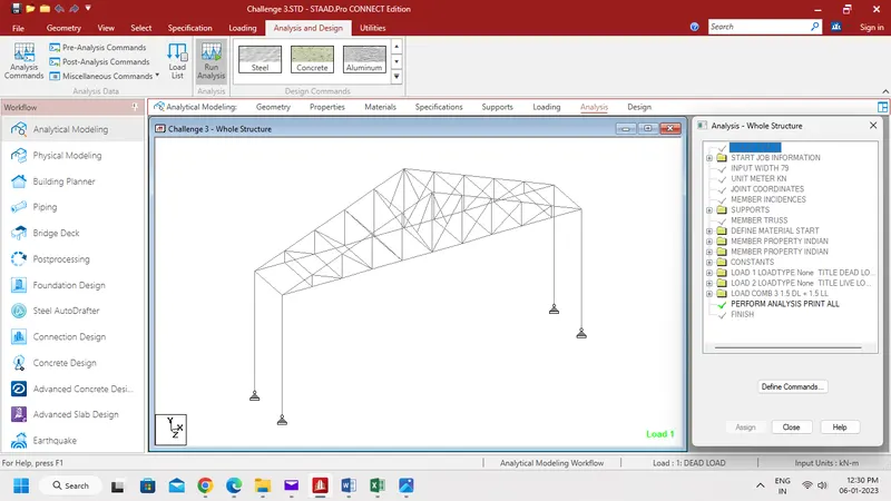
- Now click Run Analysis.
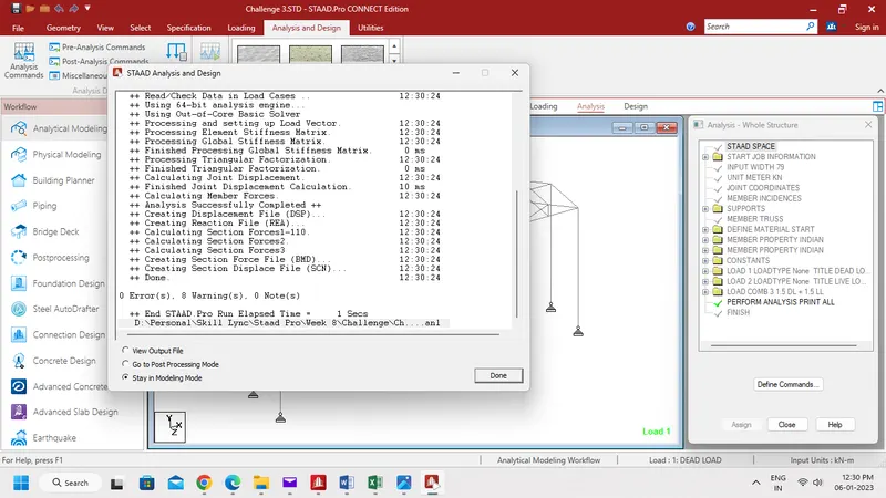
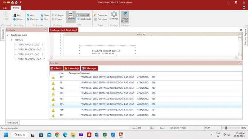
- The above Output shows 0 Errors and 8 Warnings.
- Warning shows the some members have zero Stiffness.
Step 2:-
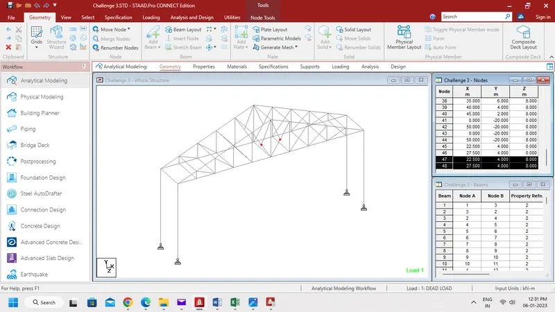
- In 47 and 48 beams having zero stiffnes.
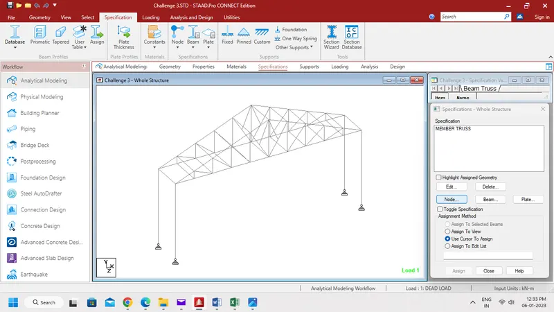
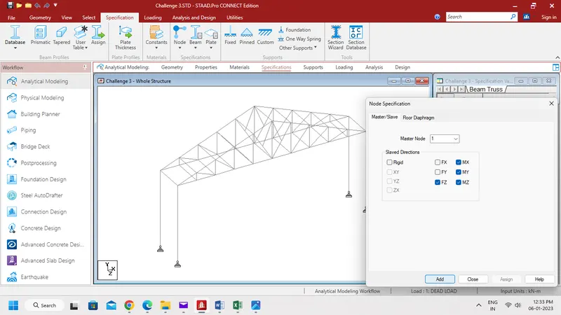
- Hence rectify it by release the Fz, Mx, My & Mz.
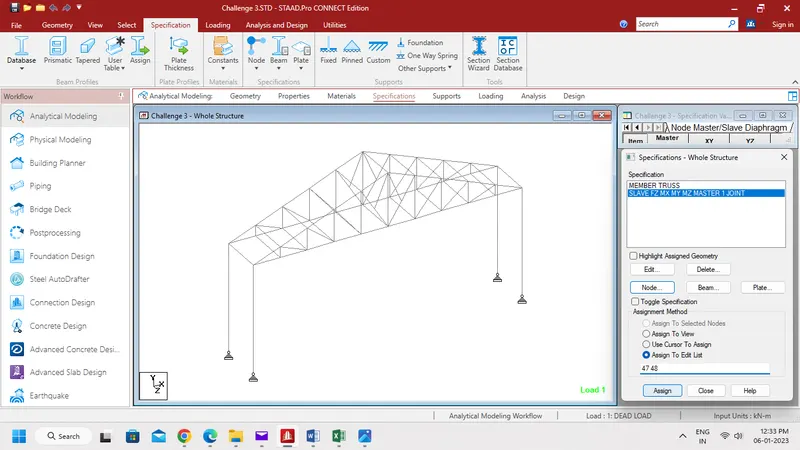
- Again Run Analysis.
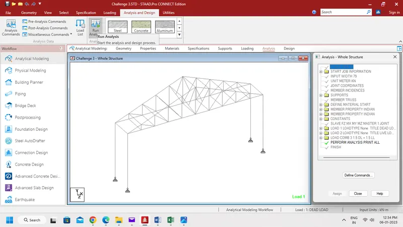
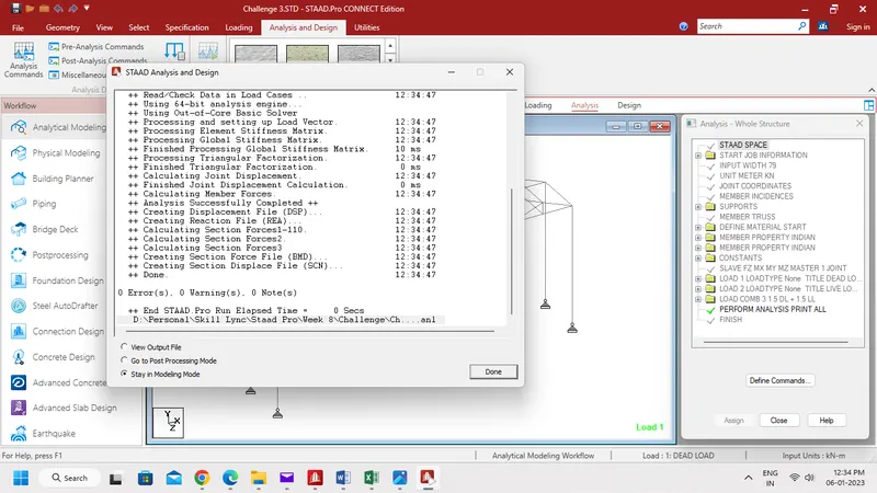
- Now output shows 0 Error and 0 Warning,
Result:-
- The given model was analysed and rectified the warinings successfully.
4. Design Parameter exercise
In continuation to challenge 1, Apply Design parameter for structure modelled for code IS800:2007.
- Effective Length Lx, Ly, Lz for beams, Truss elements
- Effective length factors Ky, Kz for Columns
- Apply other design parameters for respective members
Aim:-
To apply design parameter for the structure modelled for code IS 800 : 2007.
Procedure:-
Step 1:-
- Now go to Design tab.
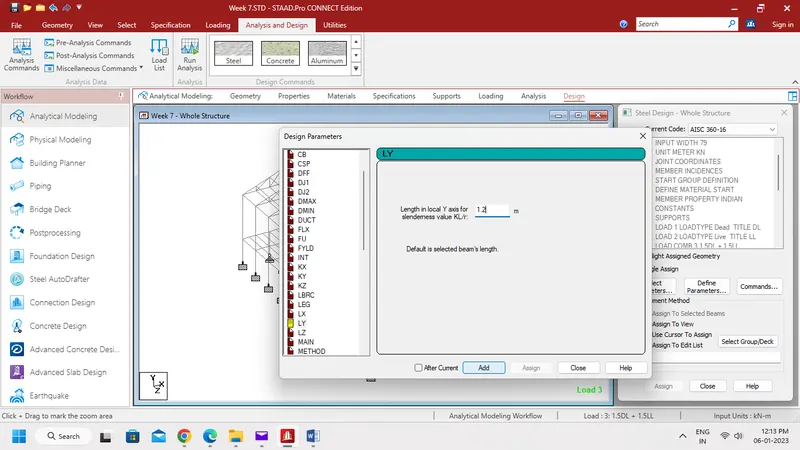
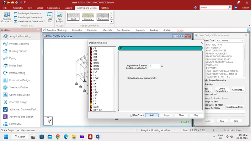
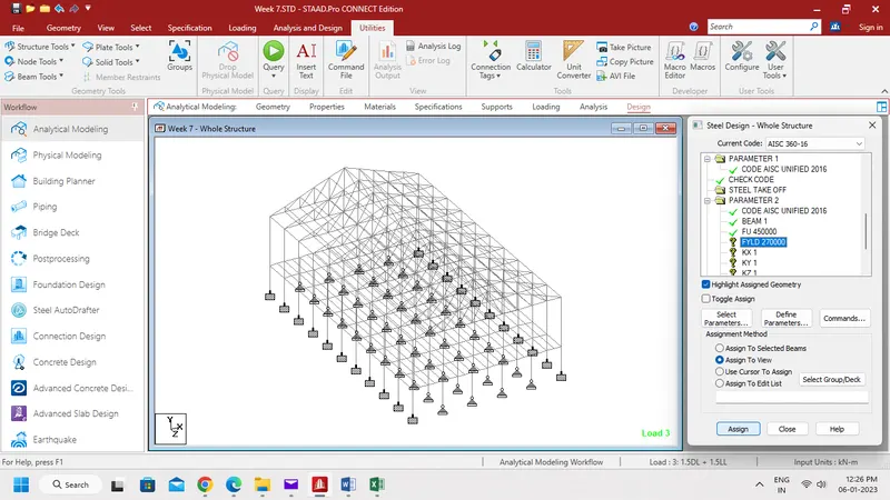
- And select Define Parameters as shown below.
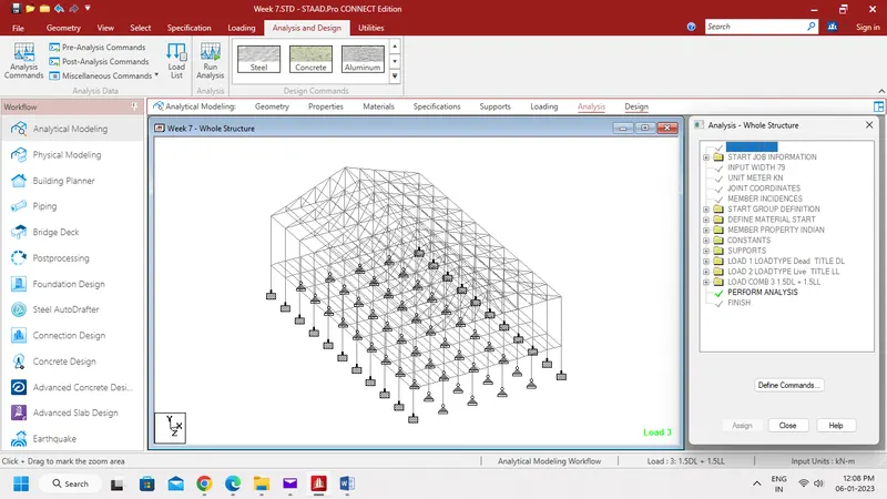
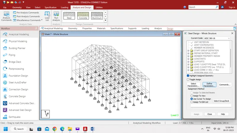
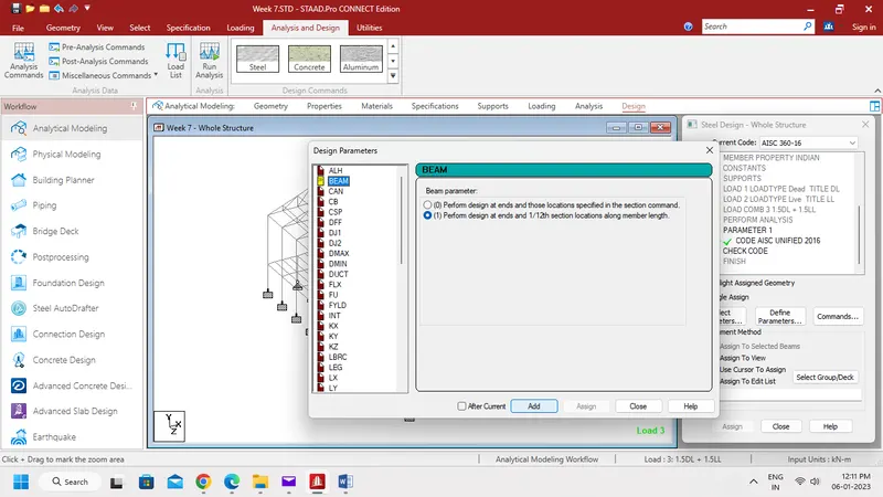
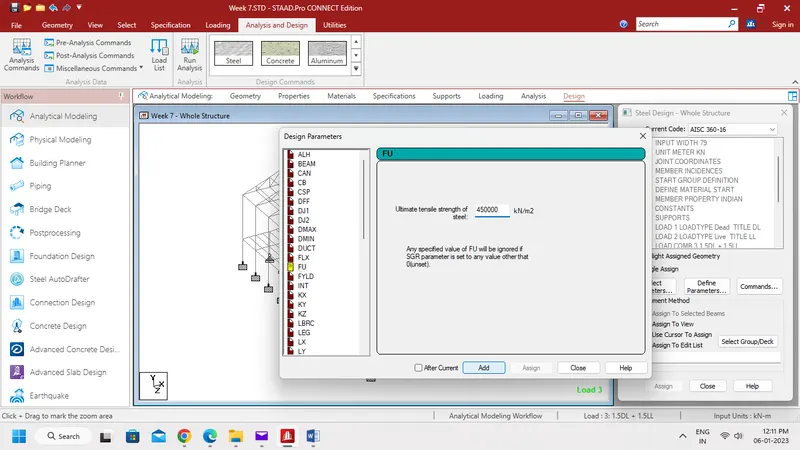
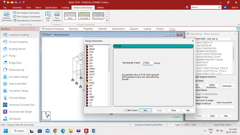
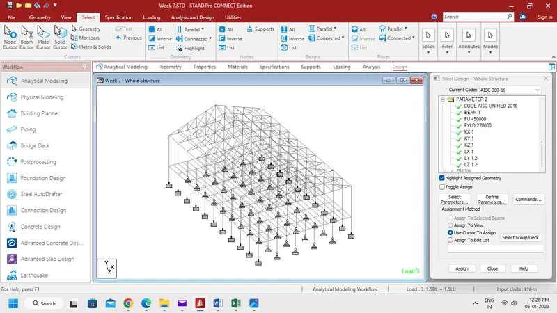
- Then define Beam, Fu, Fyld, Kx, Ky, Kz, Lx, Ly and Lz as shown below.
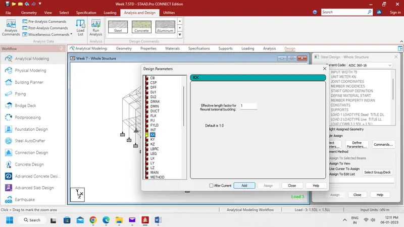
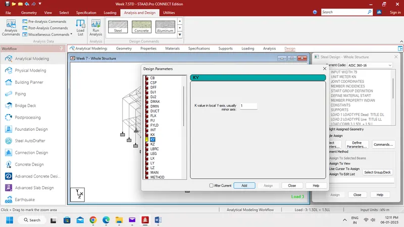
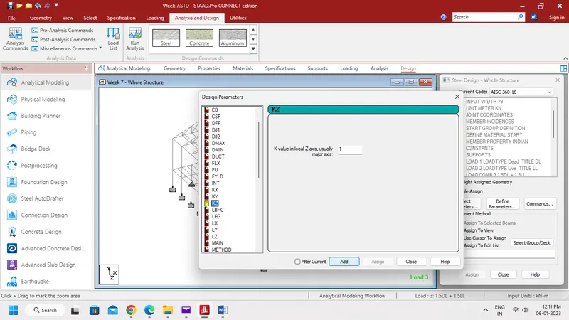
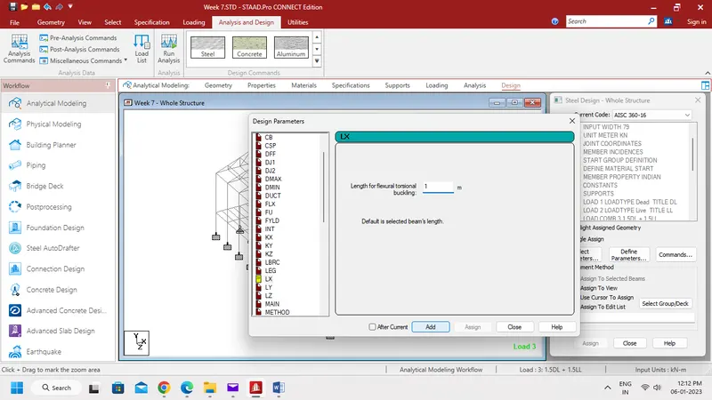
Step 2:-
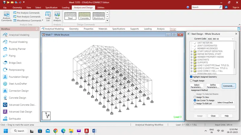
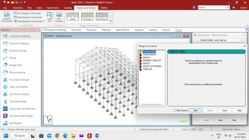
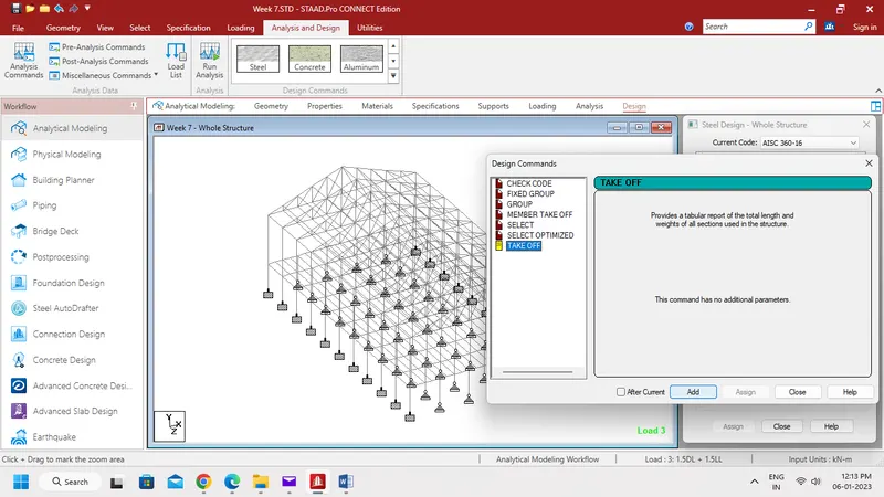
- Now select Commands, and define Check Code and Steel Take Off.
Step 3:-
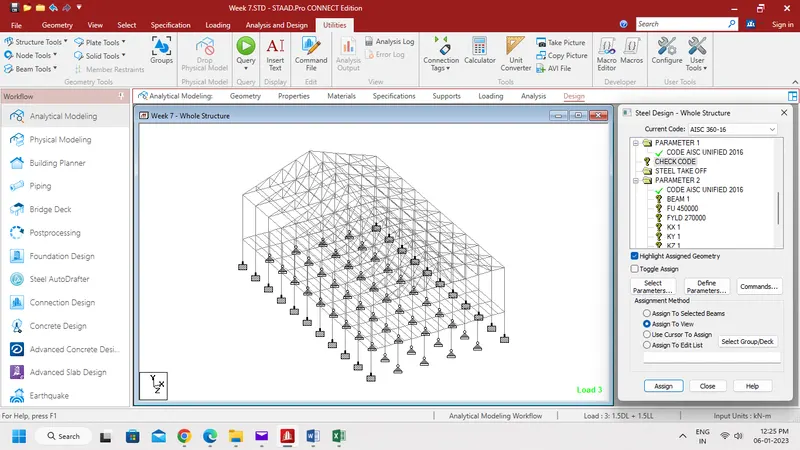
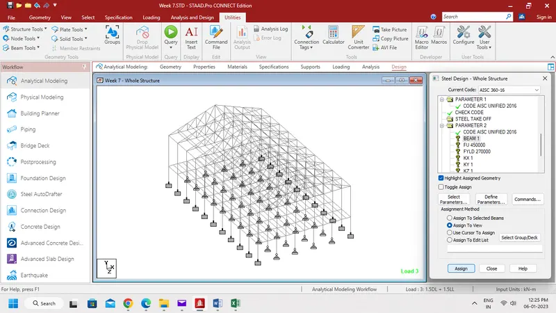
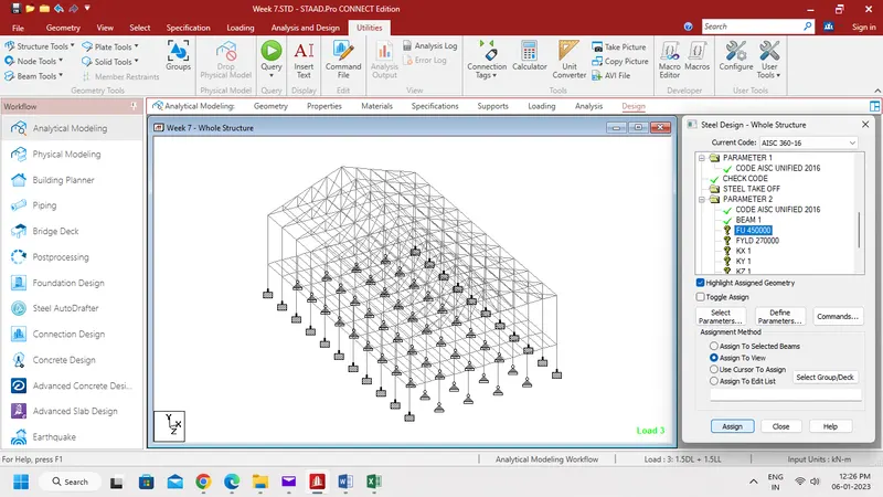
- Assign the defined parameters and Commands as shown below.
Result:-
- Design parameter for structure modelled for code IS 800:2007 was applied successfully.