Introduction to REVIT concepts
1) From the file menu, create a new project (Structural / Architectural / Construction template ) and name the project appropriately
Aim:-
To create a new project from file menu and need to name the project appropriately.
Introduction:-
Procedure:-
Step 1:
- First open the Revit software as shown below.
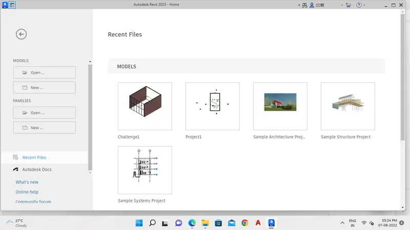
Step 2:
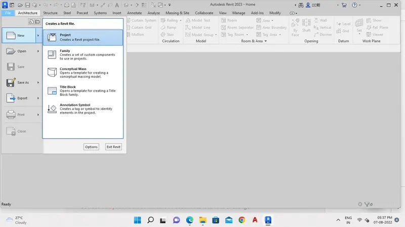
- Next select the file toolbar, the new tab appears. Then select the new tab.
- From the new tab select the Project to create a new project as shown below.
Step 3:
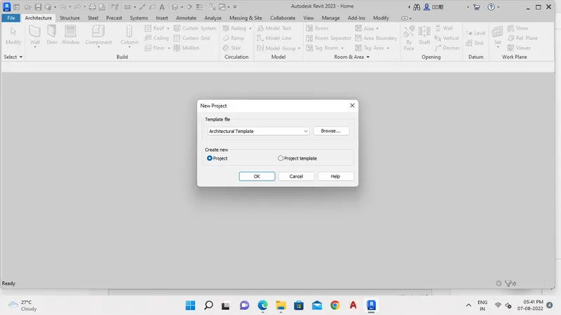
- By clicking the Project tab, the template dialog box will open.
- Then select the architecture template in the template file as shown below.
Step 4:
- Next name the project.
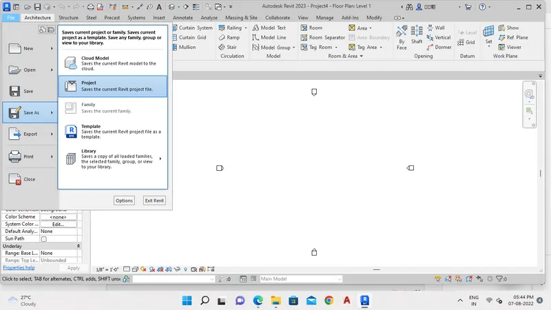
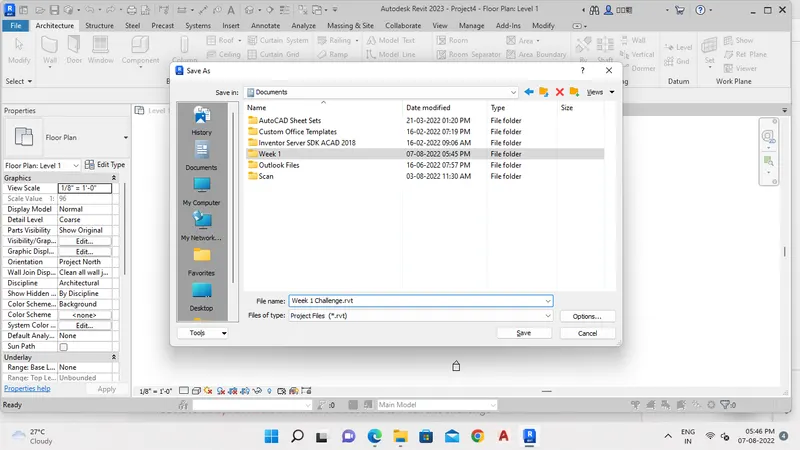
- Open the file toolbar, click on the save as option, then the new tab will appear.
- Then select the path to save the file and name the project as Week 1 Challenge.rvt as shown below.
Result:-
- Created a new projectfrom thr file menu and saved the project with the name of Week 1 Challenge.rvt.
2) Save the new project file. Close and open using icons from file toolbar
Aim:-
To save the new project file and need to close and open using icons from file toolbar.
Introduction:-
- For creating a project, select a template from the Projects list or the New project dialog box.
- Save the new project file.
- Close and reopen the project file using icons from tool bar.
Procedure:-
Step 1:
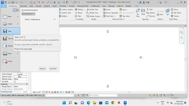
- Open the file toolbar, click on save option as shown below. Then the project file will be saved.
Step 2:
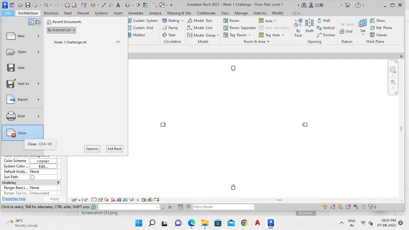
- Open the file toolbar, then click the close tab as shown below.
Step 3:
- Open the file toolbar, then click the Open tab, then click project as shown below.
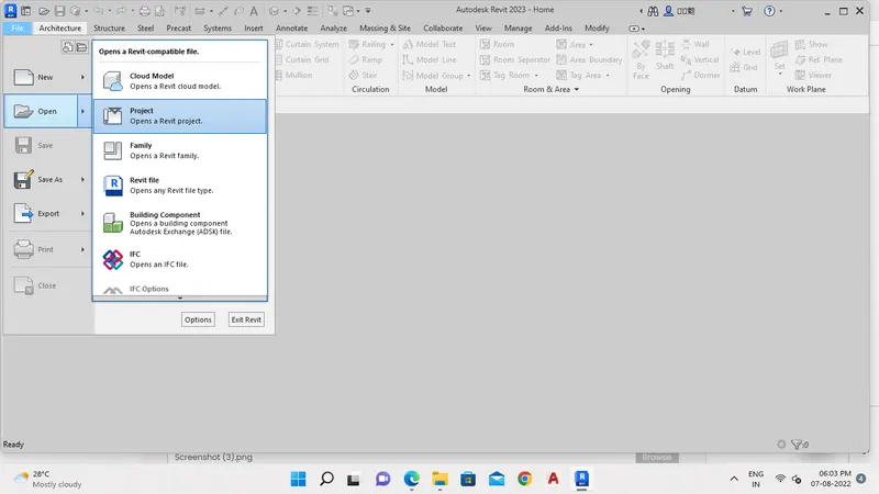
- A Open dialog box appears and then select the document path and open the Week 1 Challenge project as shown below.
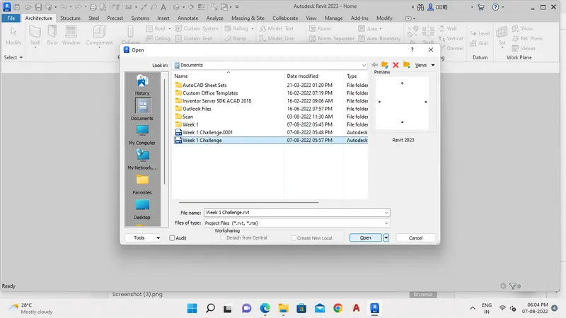
Result:-
- Created a new project from the file menu, saved the file as Week 1 Challenge and then closed and opened the same project file from the Open tab.
3) From the architecture/ structure toolbar familiarize with options to draw a wall. Create a rectangular layout of walls of about 40’-0” X 35’-0”
Aim:-
To draw a rectangular layout of walls of about 40'-0" X 53'-0" from the architecture/structure toolbar.
Introduction:-
- For creating a project, select a template from the Projects list or the New Project dialog box.
- Save the new project file.
- Create a wall as requires using the Wall tool.
Procedure:-
Step 1:
- Firtst select the Architecture toolbar, then click Wall tool as shown below.
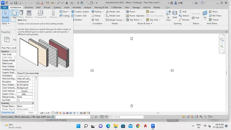
Step 2:
- From draw tool, select the line tool to draw a wall of 40"-0" X 35"-0" as show below.
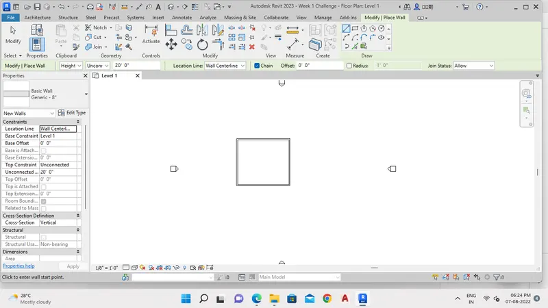
Result:-
- Created a rectangular layout of walls using the architecture toolbar.
4) From the Annotate toolbar use the aligned option to add dimensions to the layout
Aim:-
Use the aligned option to add dimensions to the layout by using annotate toolbar.
Introduction:-
- In annotate toolbar, aligned dimension to be added to the layout created.
Procedure:-
Step 1:
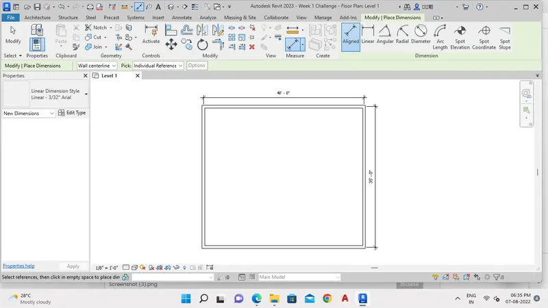
- First select the annotate toolbar and click the aligned dimension tool as shown below.
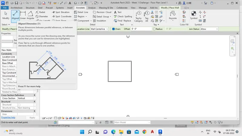
Step 2:
- Then create the demension to the rectangular layout as shown below.
Result:-
- The dimensions for the rectangular layout is added successfully using aligned option in the annotate toolbar.
5) Use the properties browser to switch to different wall types
Aim:-
To switch to different wall types using properties browser.
Introduction:-
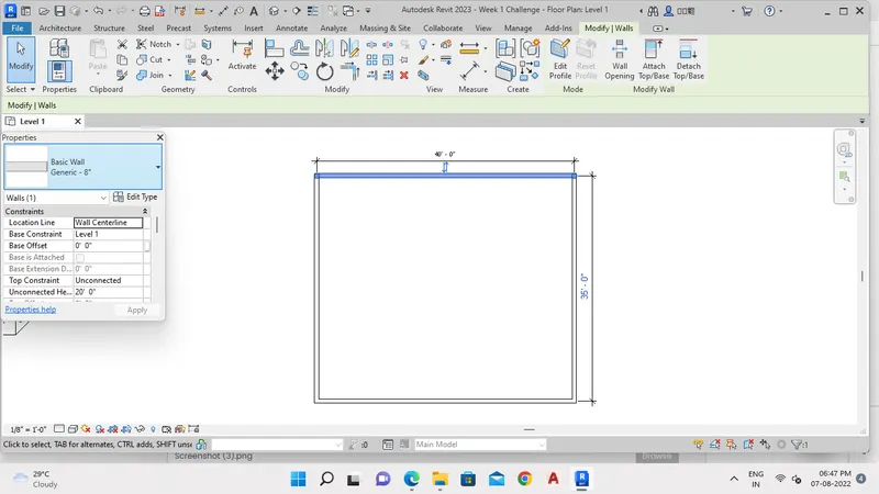
- We can change the type to the rectangular layout by selecting the particular wall.
- In properties browser there will be the different wall types and sizes.
Procedure:-
Step 1:
- Click the wall of rectangular layout, wall type appears in the properties browser as "Basic Wall Generic - 8" " as shown below.
Step 2:
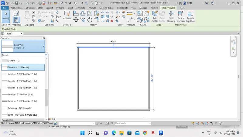
- By clicking the wall type, select the wall type as "Generic - 12" Masonry" as shown below.
Step 3:
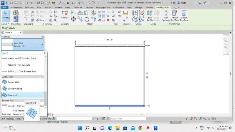
- As done, select the another wall and switch to the wall type as "Curtian Wall Storefront" as shown below.
Result:-
- From the properties browser the walls are switched to different sizes and types.
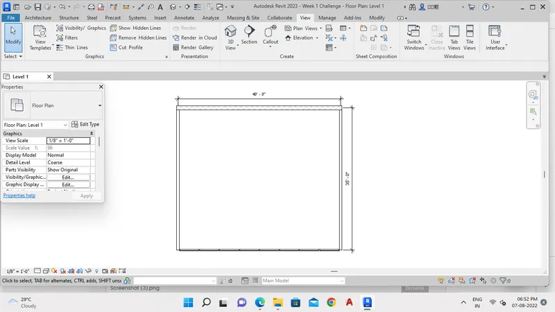
6) Create a 3D view from the view toolbar and save the view with the appropriate name
Aim:-
To create a 3D view from the view toolbar and need to save the view with the approciate name.
Introduction:-
- In view toolbar, we can see different options.
Procedure:-
Step 1:
- Select the view toolbar, then click 3D view option as shown below.
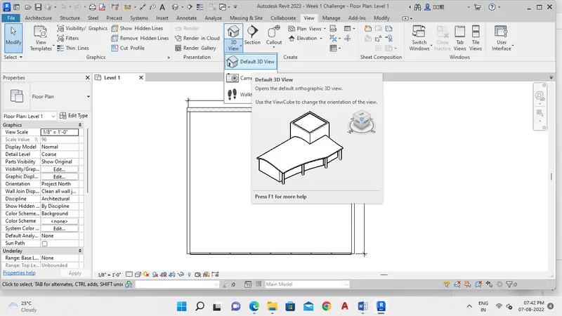
Step 2:
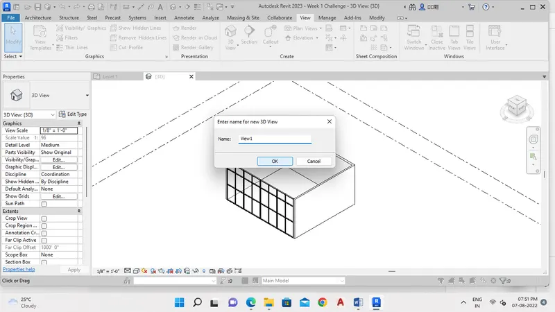
- Next place the cursor on the view cube and then right click, the new box appears and click the save view tab.
- And name the view as "View1" as shown below.
Result:-
- Created a 3D view from the view toolbar and saved the view as View1.
7) Navigate through the 3D model using the view cube. Orbit/pan through the model layout created
Aim:-
Use the view cube to navigate through the 3D model and orbit/pan through the model layout.
Introduction:-
- View cube is used to navigate through the 3D model in any direction.
- Navigation bar is used to Orbit,zoom & pan the 3D model.
Procedure:-
Step 1:
- By click or drag the view cube on Top, Left, Right,etc., to navigate the 3D model to any direction as show below.
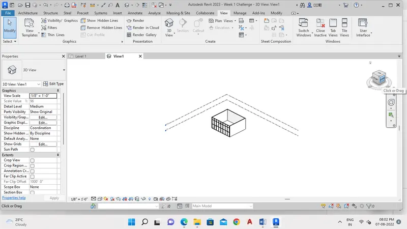
Step 2:
- In view toolbar, click User interface option to on navigation bar.
- A steering wheel appears on the right side of window.
Step 3:
- Open steering wheel as shown below.
- Aftering opening the steering wheel we need to select the orbit option, then hold the cursor and rotate the 3D model view to the different directions, as shown below.
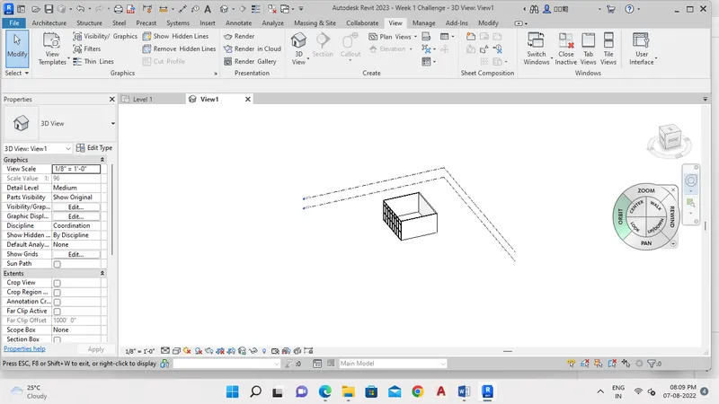
- Then click and hold the cursor at Pan to move the 3D model.
Result:
- The 3D modle is navigated using the view cube, orbit and pan options by holding them with the cursor.
8) Use the visibility settings option below to switch model to shaded, realistic, hidden lines options
Aim:-
To switch model to shaded, realistic, hidden lines options by using the visibility settings.
Introduction:-
- Using the visibility settings we can change the visibility of model, such as
- Wireframe
- Hidden line
- Shaded
- Consistent colours
- Realistic
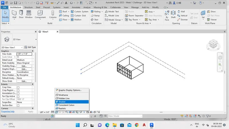
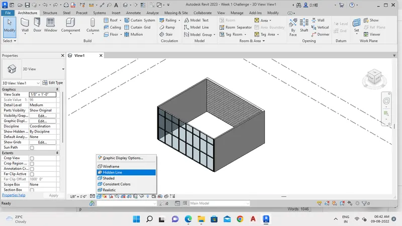
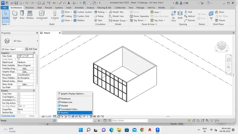
- Here we need to change visibilty of 3D model to the following three types
- Shaded
- Hidden line
- Realistic
Procedure:-
Step 1:
- At the bottom, click visual option and then select Shaded tool as show below.
Step 2:
- In visual option, select Hidden line tool as shown below.
Step 3:
- In visual option, select Realistic tool as shown below.
Result:-
- The visibility of the 3D model is successfully switched to Shaded, Hidden line & Realistic.
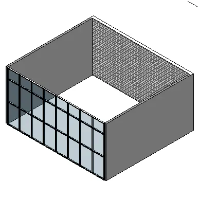
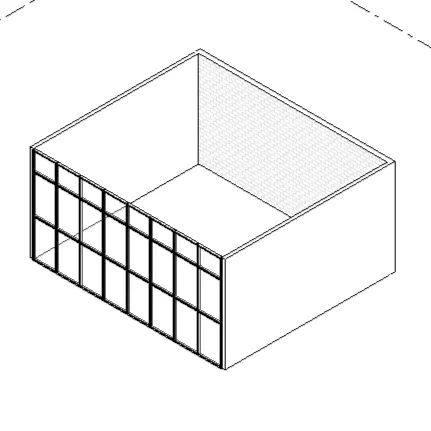
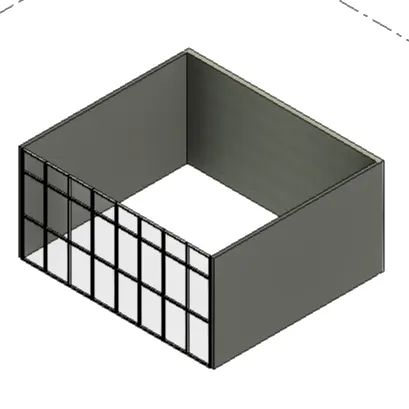
Shaded Hidden line Realistic
9) Turn the sun path on and off to view shadings in the layout created
Aim:-
To turn the sun path on and off to view shadings in the layout.
Introduction:-
- The sun's movement is an most important consideration when designing high-performance buildings.
- To understand the impact of the solar position on your bui;ding, you can use the sun and shadows settings in Revit to visualize the position of the sun at your location at any time of the day using the network map.
Procedure:-
Step 1:
- At the bottom, click the sun path icon and then select the sun settings as shown below.
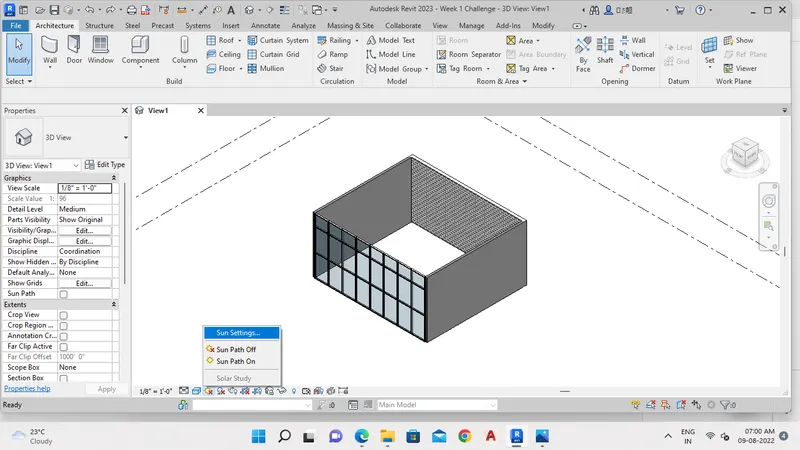
- In sun settings, Select single day at solar study option as shown below.
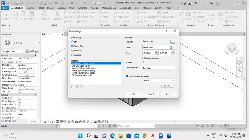
- In settings, click location one window will open select the city as chennai, India as shown below.
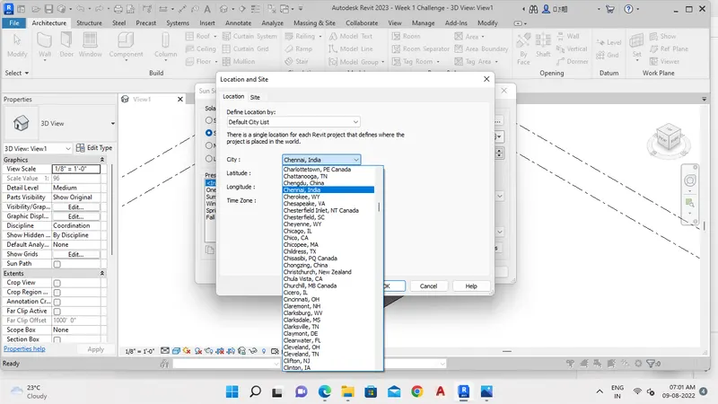
- Then apply the settings to the 3D model.
Step 2:
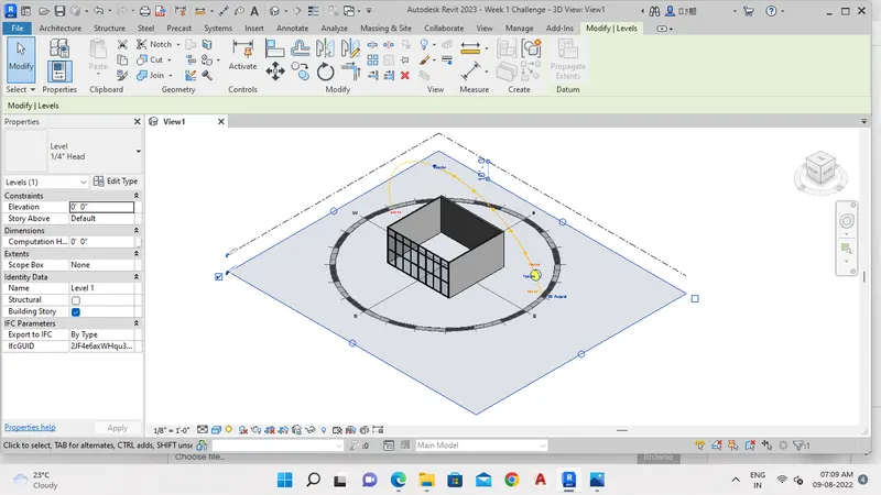
- At the bottom, click sun path option and select sun path on.
- Solar path appears around the model as shown below.
Step 3:
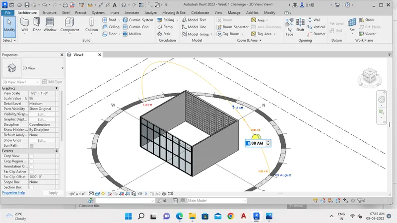
- We can change the sun location to view the shades at which time need by drag the sun or change the time as shown below.
Step 3:
- At bottom, click sum path option and select sun path off tool to off the sun path.
Result:-
- The sun path is turned on and off, that displays the ground compass, the position of sun, time of day, and time of year.
10) Use the Manage toolbar to enter project settings, project name, and project issue date (choose according to your convenience)
Aim:-
Use the manage toolbar to enter project settings, project name and project issue date.
Introduction:-
- In the manage toolbar we can see different options as shown below.

- In this options, Project information tool used to add or change the project name and project issue date.
Procedure:-
Step 1:
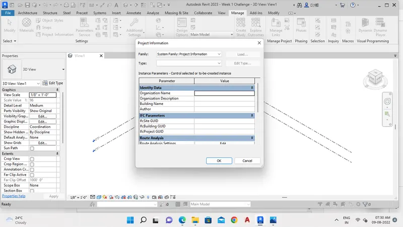
- In manage tool bar, select Project information tool, a pop up window will open as shown below.
Step 2:
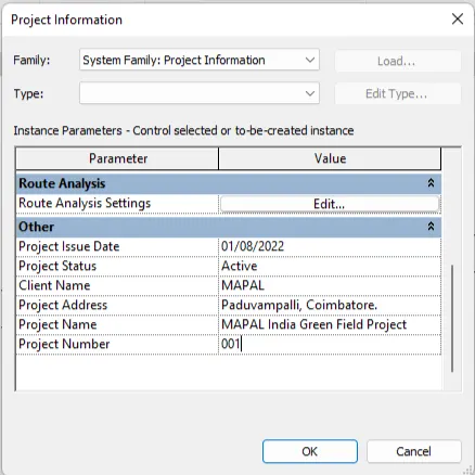
- Enter the details of the project in the Project information window as shown below.
Result:-
- The project details are entered in to the Projection information by using Manage toolbar.
11) What is the Analyze toolbar used in Revit? How it is beneficial for design and modeling
Analyze toolbar used in Revit and its benefical for desing and modelling:
- In Analyze toolbar, we can see the following tools as shown below.

- Analyze toolbar helps you to perform analysis on your structural building. The boundary conditions enable you to define point, line and area boundary conditions in an analytical model. We can add loads such as Point load, linear load, etc., to our model.
- Also we can add load combinations to our model.
- Also it enables to evaluating the energy or energy optimization of the building model.
12) What are the links that Revit supports to be linked to the model?
The links that Revit supports to be linked to the model:
- In Insert toolbar, we can see the following options that linked to the model.
- Link Revit
- Link IFC
- Link CAD
- Link Topograhy
- Manage links
Link Revit:
- This allows to link another Revit modle to the current model. For example: we can link the models together to specify the relative individual building on a campus or to coordinate efforts across several disciplines (Architectural, Structural and Plumbing, etc.,)
Link IFC:
- To link IFC file to current model to reference its information for additional design work.
Link CAD:
- We can link 2D cad file to current model to create 3D model by revit tools.
Link Topography:
- It allows to add topography map to the model.
Manage Links:
- It provides feature to manage the links to the building models.
- We can add or remove links from the current model.
13) Why do you need the Collaborate tab in Revit? How it supports modeling and its efficiency
The Collaboration tab in Revit and its efficiency:
- Collaboration tab in Revit enables the work sharing.
- Through work sharing, we can work together by local area network in a same Revit model.
- Collaborate tab helps to work together, cloud sharing, work sharing and central model.
- For work together multiple Revit models can be linked together and allowing to work in context.
- For work sharing enabling work sharing involves creating master project model known as central model from the existing model.
- The central model stores the current ownership information of all works and elements in the project and act as the distribution point for all the changes made to the model.
- Revit is really useful for MEF engineers and also who needs to collaborate with other discipline and also support the modelling.
- It allows the user to divide model into worksets, which can be editable or not editable by the current user to avoid confussion and lesser computing load.