Creating Levels, Grids, Layout and model elements for a residential unit using REVIT
1) What is BIM? Summarize the features of BIM and benefits of using BIM over 2D CAD tools.
BIM:-
BIM stands for Building Information Modelling. Building information modelling is a process supported by various tools, technologies and contracts involving the generation and management of digital representations of physical and functional characteristics of places.
It is a highly collaborative process that allows architects, engineers, real estate developers, contractors, manufacturers, and other construction professionals to plan, design, and construct a structure or building within one 3D model.
Features & Benefits of BIM:-
- Improve Onsite Collaboration and Communication
- Model-Based Cost Estimation
- Visualize Projects in Preconstruction
- Better Coordination and Clash Detection
- Mitigate Risk and Reduce Cost
- Improved Scheduling/Sequencing
- Increase Productivity with Prefabrication
- Better Safety on Construction Sites
- Execute Overall Better Builds
- Streamline Facility Management and Strengthen Building Handover
2) Understand the concept of Categories, Families, Elements, Instances in Revit. Go to Insert Tab, choose a category. Pick a family and element. Understand the instances and insert it to Revit model
Aim:-
To understand the concept of Categories, Families, Element and Instance in Revit. And insert a instances in to a Revit model.
Introduction:-
Categories: A Category controls the organization, visibility, graphical representations, and scheduling options of Families within the Project.
Families: A Family is a grouping of 2D and/or 3D information that serves to represent a discrete building or documentation element in the Project. It defines parametric, graphical, and documentation requirements.
Type: A Type is a specific representation in a Family defined by distinct parametric, graphical, and documentation characteristics which makes it unique from other Types in the Family.
Instance: An Instance is an individual representation of a Type in the Project defined by unique parametric, graphical, and documentation characteristics which makes it unique from other Instances in the Project.
Procedure:-
Step 1:-
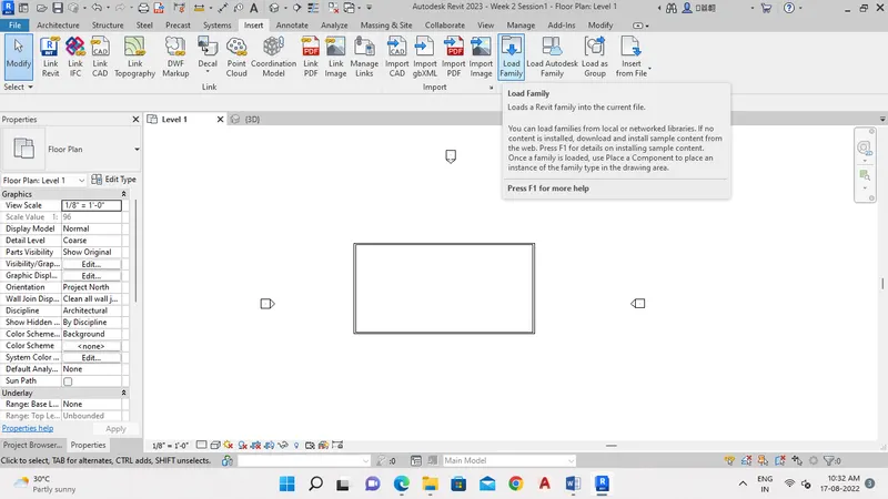
- Open a model in revit software, go to Insert Tab and click Load Family as shown below.
Step 2:-
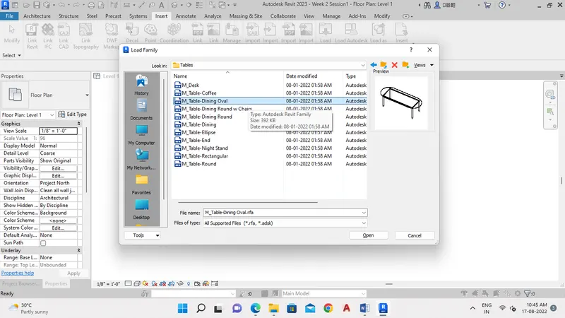
- In Load Family pop-up window, select US folder and click the furniture folder.
- In furniture folder, select table folder, select the table wanted as show below. And then click open.
Step 3:-
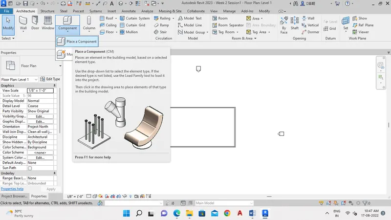
- Go to Architecture Tab, and click component tool for insert a table element as shown below.
Step 4:-
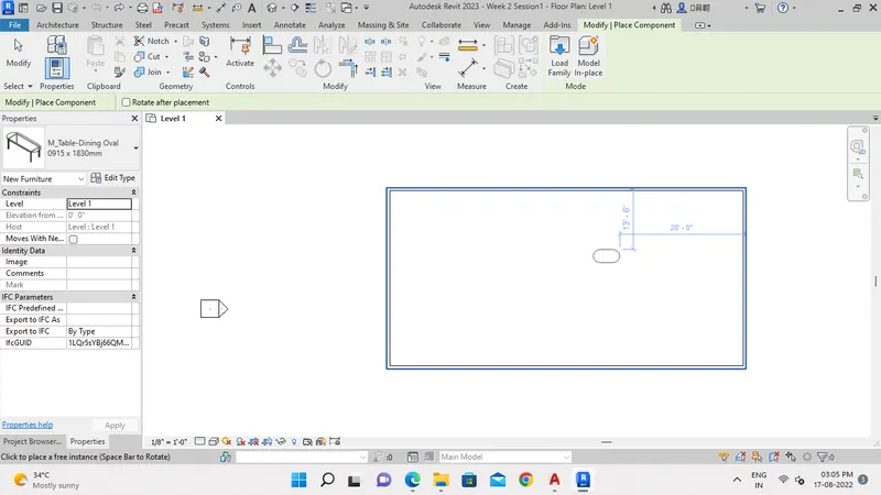
- In proprerties browser, select the M_Table-Dining Oval and place the table in the model as shown below.
Result:-
- Understood the concept of Categories, Families, Elements and Instances.
- The table element succesfully inserted into the model.
3) Setting up a Project – Open a project file with architectural template. Save the file with appropriate name. Set up the project units to Imperial / Metric based on your convenience of modelling. Complete the project information under Manage tab. Set up the maximum backups for project file to 3
Aim:-
To setting up a new project by using the Manage Tab and save the file with the appropriate name.
Introduction:-
- Setting up a project with necessary informations.
Procedure:-
Step 1:-
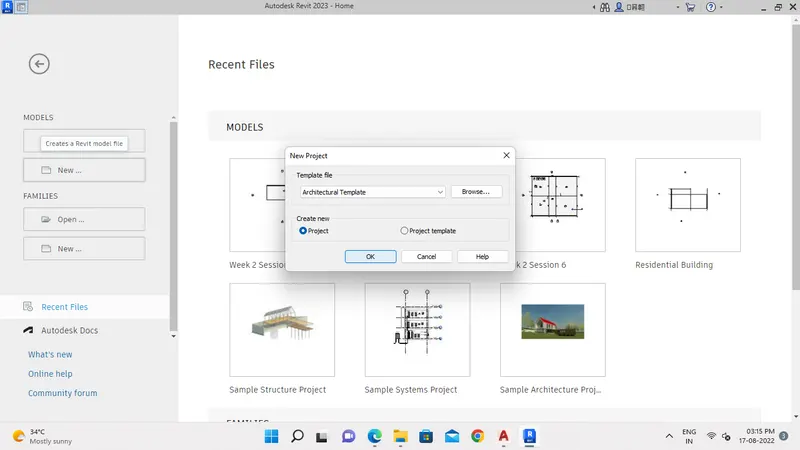
- Open a Revit software, select the New tab.
- In new tab, click Architectural Template as shown below. Then click ok.
Step 2:-
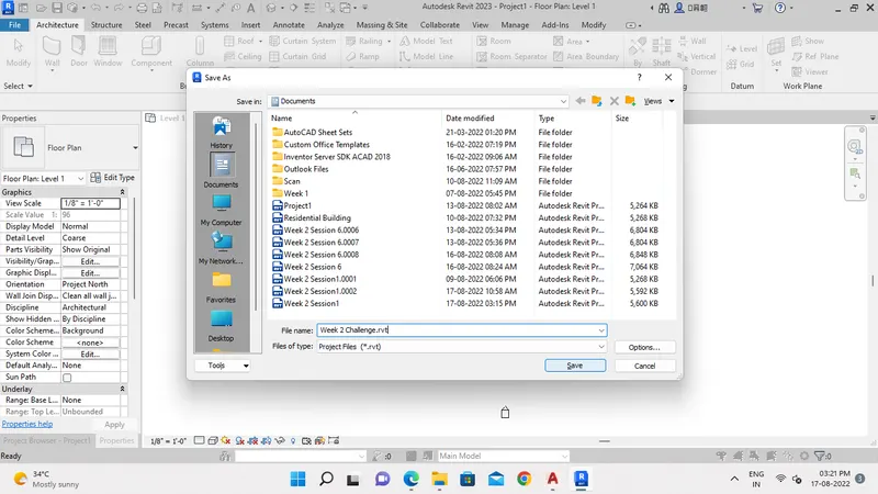
- In File toolbar, click save option. And save the file as "Week 2 Challenge" as shown below.
Step 3:-
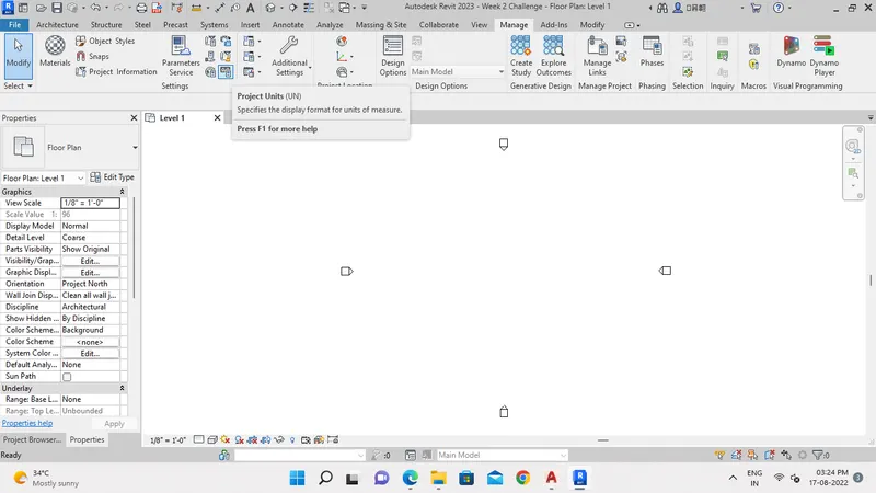
- Set up the project unit as imperial from the Manage Tool bar.
- In Manage tool bar, select Project Units.
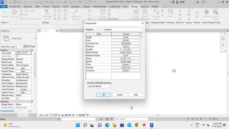
- A pop-up window apears as shown below.
- Then select the Units as imperial.
Step 4:-
- From Manage tool bar, select Projection Information tool as shown below.
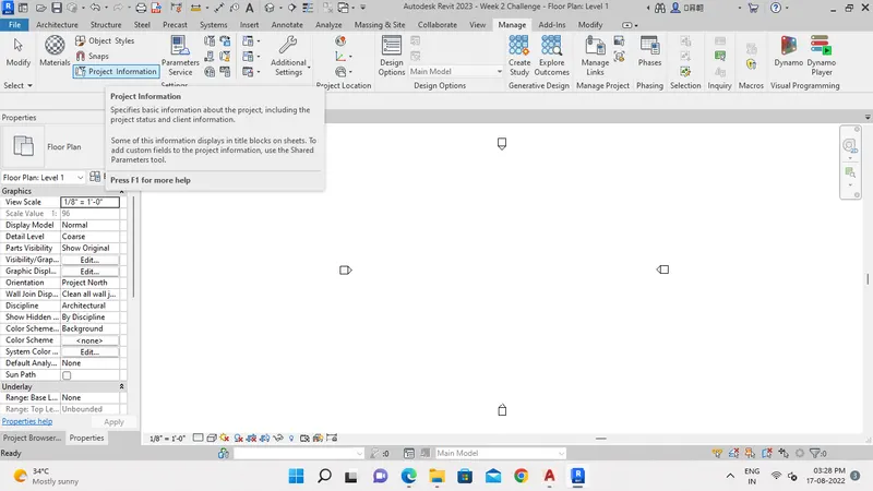
- A window appears, fill the Project information as shown below.
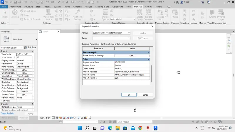
Step 5:-
- In File Tab, click Save as option and select Project as shown below.
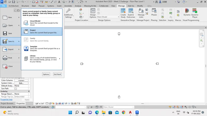
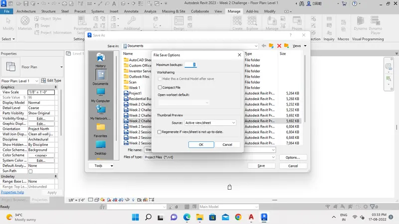
- A pop-up window appears, in that click option.
- And set the maximum backups as 3 as shown below. Then click Ok.
Result:-
- Setting ip a project was successfully completed by using Manage toolbar and Maximum Backups set ups as 3.
4) Understand the concept of Levels and Grids. Follow the naming and conventions. Create the following Levels: ( Convert to metric equivalents if metric is your units)
Ground Floor @ 0’
First Floor @ 10’
Second Floor @ 20’
Roof @ 30’
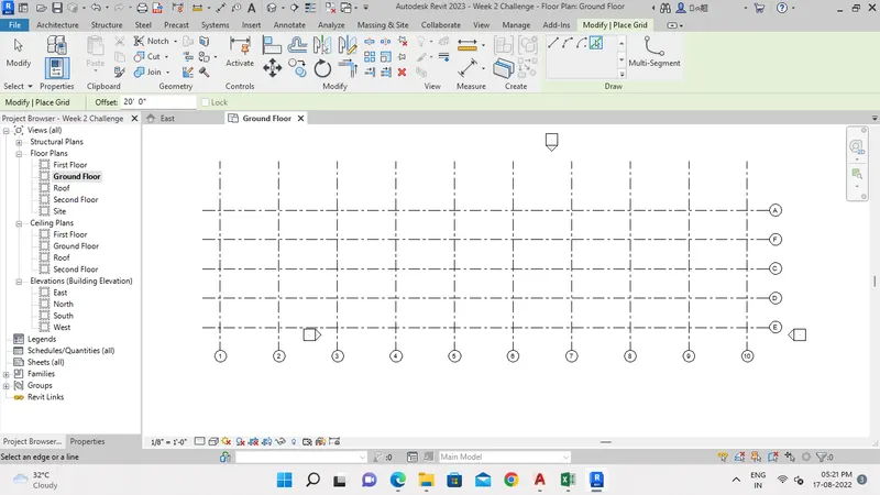
Grids Transverse Grids A, B,C,D, E @ 10’ spacing
Longitudinal Grids from 1 to 10 @ 20’ spacing
Aim:-
To understand the concept of Levels and Grids and create the following levels and grids.
Introduction:-
Levels: Levels are finite horizontal planes that act as a reference for level-hosted elements, such as roofs, floors, and ceilings. They define a vertical height or story within a building.
Grids: Grids are datum elements and there are visible in views that intersect the Grids extents. Grids can be used as references for a building model.
Procedure:-
Step 1:-
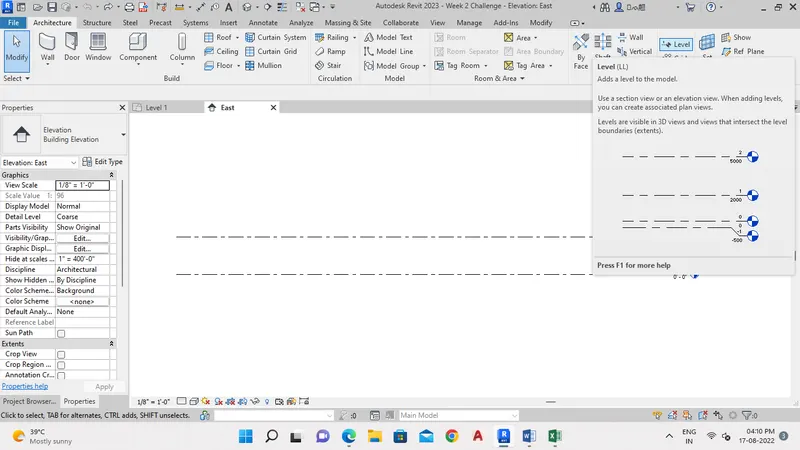
- Go to any elevation view.
- In Architecture Tool bar, select Level tool as shown below.
Step 2:-
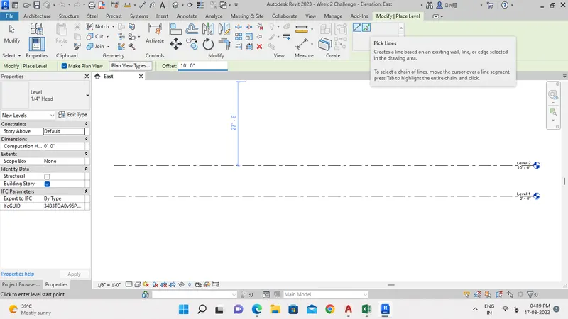
- Set an Offset as 10'0" and click Pick Lines option as shown below.
- Then select the level to be offset.
- Offset the level upto Level 4.
Step 3:-
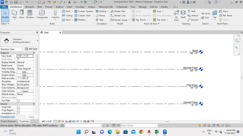
- Rename the Level 1, Level 2, Level 3 & Level 4 as Ground Floor, First Floor, Second Floor & Roof respectively.
Step 4:-
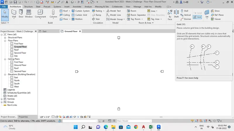
- Go to Ground Floor View.
- In Architecture Tool bar, select Grid option as shown below.
Step 5:-
- Make a Transverse grid, by clicking line option and name it as A.
- Then set offset as 10'0". And select Pick line option offset the grid line as B,C,D & E at an interval of 10'.
- Make a Longitudinal grid 1 by clicking line option and name it as 1.
- Then set offset as 20'0". And select Pick line option offset the grid line as 2 to 10 at an interval of 20'.
Result:-
- Above Levels and Grids was created successfully.
5) 3D modelling of residential unit – From looking at your house / or a place you aspire. Create a conceptual layout of the residential unit. You can measure using a tape or
you can access your residential plan to create a similar layout.
Aim:-
To create a conceptual layout of the residential unit and measure using a tape.
Introduction:-
- 3D modelling of residential unit by using Revit software.
Procedure:-
Step 1:-
- Open Revit software, then create a new Architectural project.
- Setting up a Project information using Manage tool bar.
Step 2:-
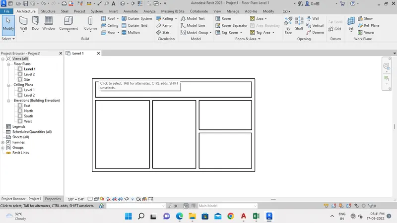
- From Architecture tool bar, select wall tool to draw the layout of residential unit.
- Draw the exterior wall for the residential unit.
- Then draw the interior wall as shown below.
Step 3:-
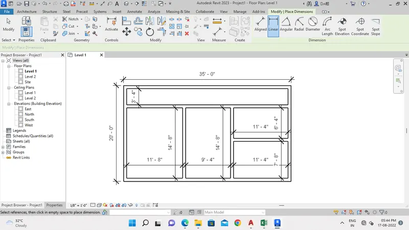
- First Measure the outer layout of model from Annotate tool bar.
- Then measure the inner area of walls as shown below.
6) In the layout created draft the level of details you are planning to include – Dimensions of room, components you plan to add in the residential unit.
Aim:-
To add dimensions of room and components to residential unit created.
Introduction:-
- Adding dimension and components to residential unit using Architecture tool bar.
Procedure:-
Step 1:-
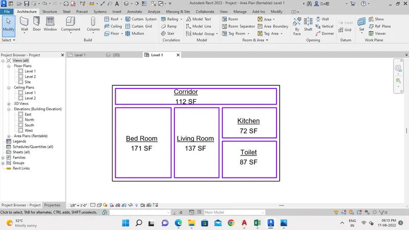
- From Architecture tool bar, select Area tool for give dimensions of room as shown below.
- From Area tool, make area boundary and give dimensions.
Step 2:-
- From Architecture tool bar, click Component tool as shown below.
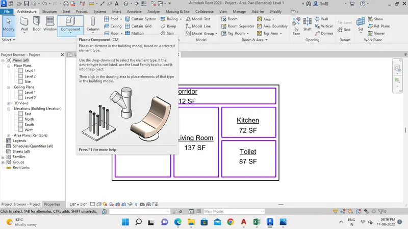
Step 3:-
- Add Furniture desk component to the residential unit from Architecture tool bar as shown below.
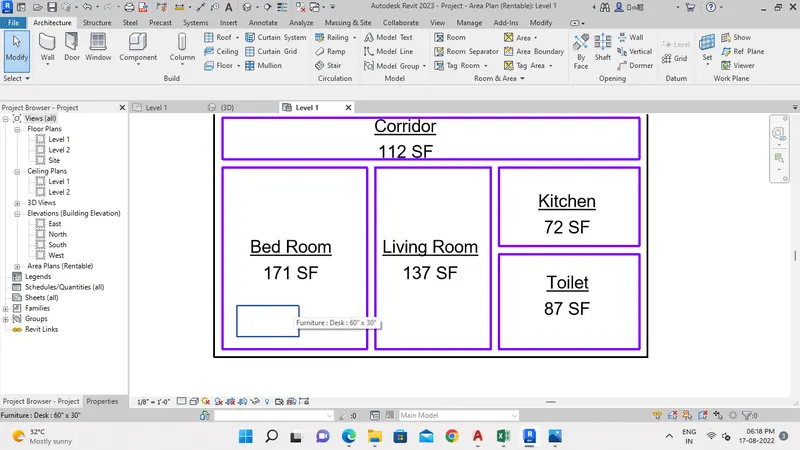
Result:-
- Dimensions of rooms added to the residential unit.
- Component insert from Architecture tool bar.
7) Identify the residential model elements such as Door, Windows, Tables, Chair, Couch, Bed, Lamps from the library and insert them to the model . Save the project for use
for Assignment 3
Aim:-
To identify the model elements such as Door, Windows, Tables, Chair, Couch, Bed, Lamps from library and insert then to the model.
Introduction:-
- Identification of elements from library such as door, window, etc,.
Procedure:-
Step 1:-
- Go to Insert Toolbar, then select Load Family.
- In US folder, We can identify the element such Door, Windows, Tables, Chair, Couch, Bed, Lamps as shown below.
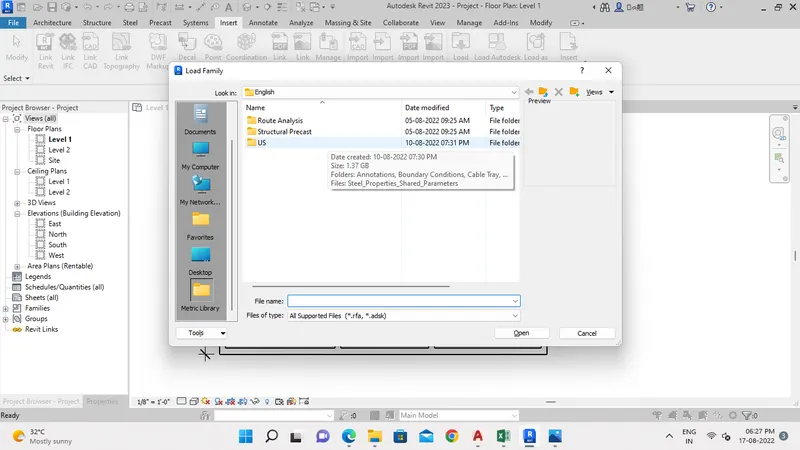
Step 2:-
- In Architecture toolbar, select Components and insert the elements Door, Window, Table, Chair & Bed as shown below.
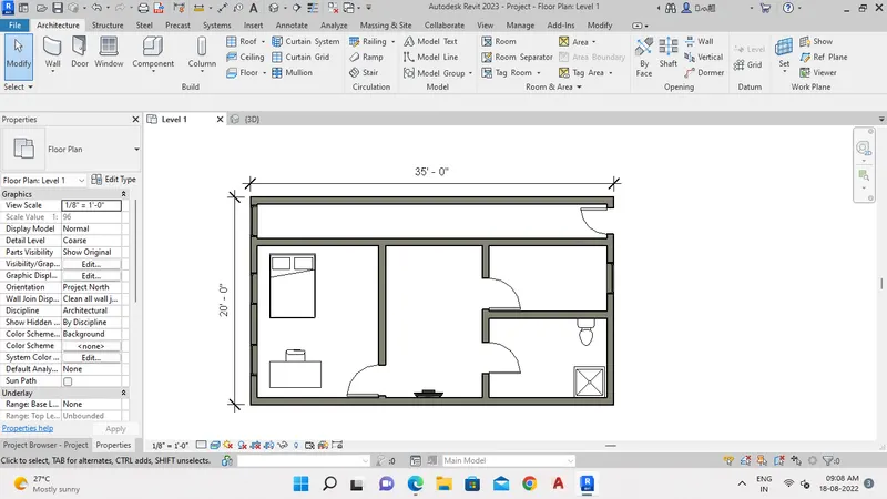
Step 3:-
- Save the Project from File Tab.
Result:-
- Identification and Insertion of Elements from the Component tools into the Model was done successfully.