Week 8 Challenge
Input Signal:
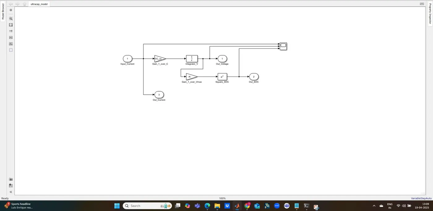
The In1 block (labeled Input_Current) represents the current entering the ultracapacitor. You can later replace this with a desired current profile.
Voltage Calculation:
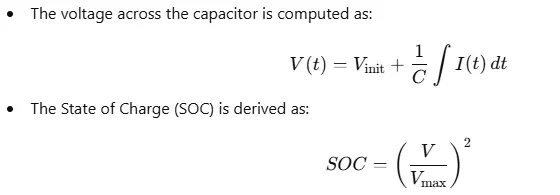
The input current is scaled by a Gain block by Cuc1 (since dtdV=CI) and fed into an Integrator block, which outputs the capacitor voltage. The integrator is initialized at the voltage Vinit.
SOC Calculation:
The capacitor voltage is first divided by Vmax using another Gain block. Then the result is squared using a Math Function block set to “square” so that SOC=(V/Vmax)2.
Outputs:
Three Out1 blocks provide the current (as it is), voltage (from the integrator), and the calculated SOC, respectively.
Stop Time:
The model’s simulation stop time is set to 598 seconds.
Output after a simulation of 598 sec:
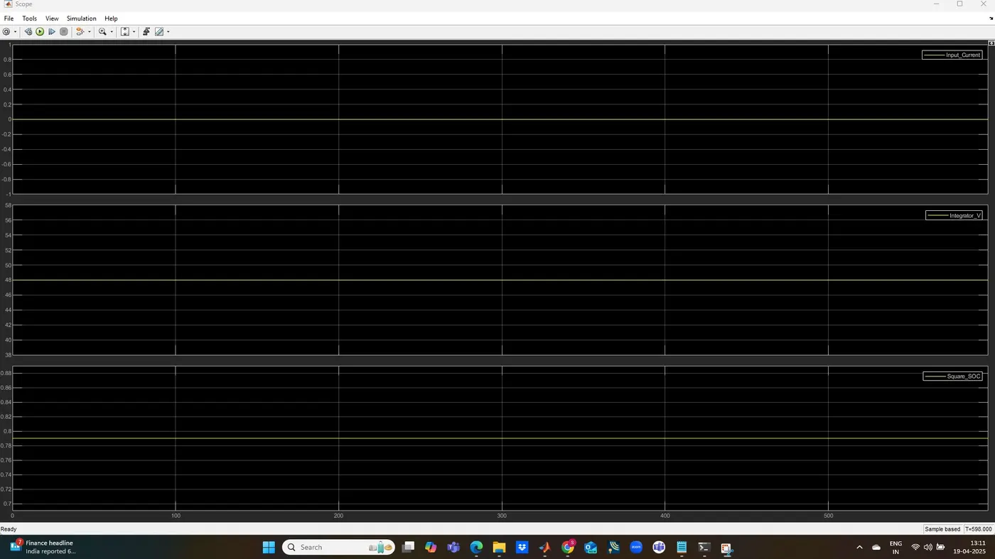
The scope output from your ultracapacitor Simulink model simulation shows the system's behavior over the 598 seconds of simulation time. Here's what each graph represents:
Input Current (Flat Line at 0):
The input current remains constant at 0 throughout the simulation. This indicates that no current was applied to charge or discharge the ultracapacitor. This is due to absence of external stimuli to the system.Integrator Voltage (Flat Line at 48 V):
The voltage across the ultracapacitor stays stable at approximately 48 V. This aligns with the initial voltage parameter ((V_{init} = 48)). Since there's no input current to charge or discharge the capacitor, the voltage remains constant, reflecting a steady state.State of Charge (SOC, Flat Line at 0.8 or 80%):
The SOC remains constant at about 80%. This value is calculated from the initial voltage and maximum voltage ((\text{SOC}_{init} = \left(\frac{48}{54}\right)^2 \approx 0.8)). With no current flowing, the SOC doesn't change during the simulation.
Overall Summary:
The simulation results suggest that the system remains in a steady state with no dynamic behavior. This is because the input current is zero, leaving the ultracapacitor at its initial voltage and SOC throughout the entire simulation period.
If your intention was to observe dynamic charging or discharging behavior, you might need to introduce a non-zero current input or vary it over time.