Project
OBJECTIVE:
1.To analyze the ATV model in system level environment using matlab & simulink.
2.To study the behaviour of the system to different simulated inputs & parameters through characteristics & plots.
3. To analyze the model,justify & explain in detail the different simulink & simscape blocks used.
REPORT:
1. What is a CVT system ?
CVT (Continuously Variable Transmission) is a system with seamless(stepless) gear transmission. It maintains optimum efficiency in engine rpm according to vehicle speed, resulting in improved vehicle fuel economy. At the same time, CVT is also characterized by its smooth acceleration & deceleration unlike the conventional manual gear system where one can feel the gear transition in the form of small jerk & vibration.
The CVT is an automatic transmission that uses two pulleys with a steel belt running between them. To continuously vary its gear ratios, the CVT simultaneously adjusts the diameter of the "drive pulley" that transmits torque from the engine and the "driven pulley" that transfers torque to the wheels.
Firstly we will analyze cvtModel.slx model:
Explaining the blocks in the model(cvtModel.slx)-
- The CVT model is created using both simscape & simulink blocks.The simscape blocks used are generic engine,CVT,Simple gear,engine speed sensor & Vehicle body and the simulink blocks used are signal builder blocks,Goto & from tags,Scope.
The PS-Simulink & Simulink-PS convertors are also used to convert simscape physical signals to simulink signals & simulink signals to simscape physical signals respectively.
- The brake input to the vehicle & throttle input to the engine is given using a signal builder block.
- When throttle is increased there is more fuel injection & more is the energy generated after combustion so the speed of the engine increases so does the vehicle speed.
- The speed of the engine is sensed by the engine speed sensor & the sensor input is given to the CVT.
- The CVT block here is for the continuosly variable transmission system block.A CVT is an automatic gear system but it doesn't involve the physical gears as with the conventional manual transmission.
- A CVT consists of a 2 conical pulley system(primary & secondary pulley) connected with a mettalic belt.The distance between the 2 pulleys is fixed. But the width of the pulleys can be controlled using a seperate electronic controller depending on the speed input recieved from engine speed.Based on the width of the pulleys the effective diameter of the pulley is changed & so is the speed of the primary & secondary pulleys.
- for a given engine speed the If the width of the primary pulley is more than the width of secondary pulley the speed of the secondary pulley is less than that of the primary pulley & this is called underspeed condition & this will slow down the vehicle.
- If the width of the primary pulley is less than the width of secondary pulley the speed of the secondary pulley is more than that of the primary pulley & this is called overspeed condition & this will speed up the vehicle.
- If the width of primary & secondary pulley is equal then the speed of primary & secondary pulley is the same.
- The width of the primary pulleys is automatically changed based on the speed of the vehicle.
- There are 2 inputs to the CVT simscape block: one is the range of CVT ratio fia via signal builder block & the second is the engine speed value coming from the engine speed sensor.
- Based on the engine speed the corresponding CVT ratio is selected & accordingly the speed of the driveshaft & the vehicle changes.
- Using the from tags The vehicle speed,displacement,throttle & brake values are displayed in the scope & similary the speed of the primary & secondary pulley of the CVT is also displayed in the scope.
2. Analyzing cvtModel_dashboard.slx model:
- The same model can be added with GUI using dashboard in simulink to display RPM,brake input,throttle input & vehicle velocity. These GUI blocks are then mapped with the related signals so that the GUI changes accordingly with given inputs.
- instead of giving Throttle & brake inputs from signal builder, constants blocks can be used to give numerical inputs.
- Rest of the behaviour same as the first model discussed.
3. Analyzing cvtModel_cvtratio_rpm.slx model:
- we can collect the range of different CVT ratios for different engine RPM's and using this data we can plot a lookup table.Based on the value of engine RPM from engine sensor the corresponding value of CVT ratio is chosen & based on the interpolation or extrapolation it is given as an input to CVT system and accordingly the output speed of the vehicle will be calculated.
- Rest of the behaviour same as the first model discussed.
4. Analyzing:cvtModel_dashboard_mapped.slx model:
- Instead of placing lookup table outside CVT system block,the lookup table with CVT-Engine RPM relation is now placed inside CVT system block & speed input is given as a closed loop feedback collected from the moving vehicle & fed back to electronic controller of CVT system.It is similar to a closed loop control system.
- The engine RPM,brake input,throttle input & vehicle velocity are displayed as GUI using dashboard in simulink
5. Analyzing cvtModel_mapped.slx model:
- Instead of placing lookup table outside CVT system block,the lookup table with CVT-Engine RPM relation is now placed inside CVT system block & speed input is given as a closed loop feedback collected from the moving vehicle & fed back to electronic controller of CVT system.It is similar to a closed loop control system.
OUTPUT CHARACTERISTICS:
1.cvtModel.slx
CASE1:
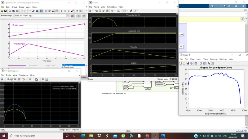
1.If the throttle is increased for sometime & decreased steadily and also Brake input is steadily increased then the vehicle velocity first increases and steadily decreases & also distance covered first increases then becomes steady at a later stage.
2.During increasing throttle, speed of secondary pulley of CVT>speed of primary pulley of CVT(overspeed condition).During decreasing throttle, speed of secondary pulley of CVT
3. finally the speed becomes zero at some point of time if there is no throttle after a period of time.
4. The deceleration of the vehicle happens faster with braking force steadily increasing.
5. At lower engine RPM/At starting speed the torque is high which helps the vehicle to pickup faster with high starting torque.High torque helps vehicle in mountaineous and hilly roads.
CASE2:
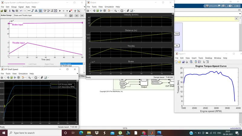
1.If there is no brake input & the throttle is gradually increased then gradually decreased the vehicle speed first increases then becomes steady(constant) for some time & then vehicle starts decelerating.
2.During increasing throttle, speed of secondary pulley of CVT>speed of primary pulley of CVT(overspeed condition).During decreasing throttle, speed of secondary pulley of CVT
3. finally the speed becomes zero at some point of time if there is no throttle after a period of time.
4. The deceleration of the vehicle happens slowly with no braking force applied.
5. At lower engine RPM/At starting speed the torque is high which helps the vehicle to pickup faster with high starting torque.High torque helps vehicle in mountaineous and hilly roads.
2. cvtModel_dashboard
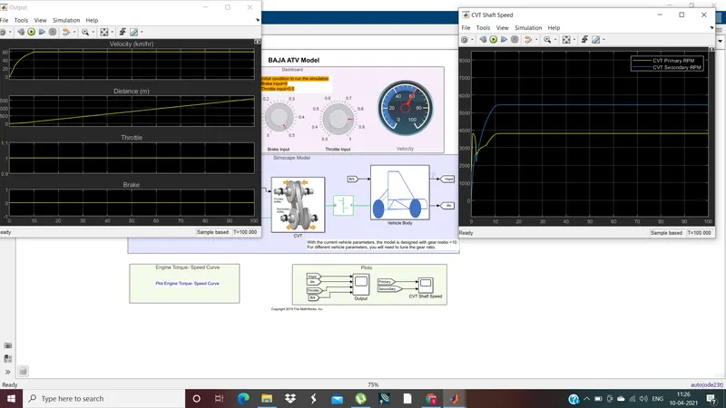
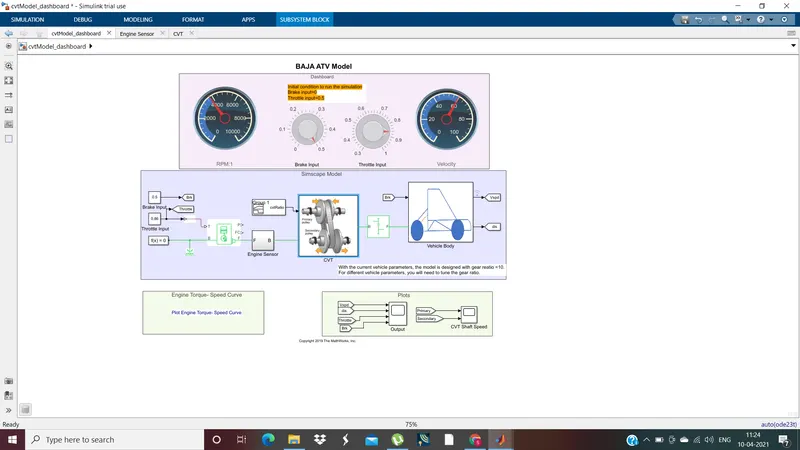
- On giving the brake & throttle inputs via constant blocks the RPM & vehicle velocity is displayed by dashboard GUI.
- The output characteristics like velocity,distance travelled,CVT primary & secondary speeds can be explained the same way for the first model.
3. cvtModel_mapped
CASE1:
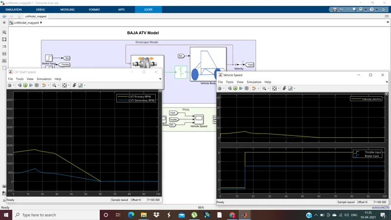
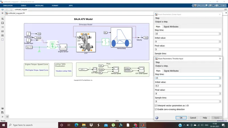
- In the case of this model the brake and throttle inputs are step inputs.Till the period the throttle is increased the vehicle speed increases correspondingly after that the vehicle starts decelerating
- The CVT undergoes underspeed scenario due to braking applies in parallel to throttle.After some time the CVT primary & secondary speeds equalize as shown by the CVT plot where primary & secondary curves overlap.
CASE2:
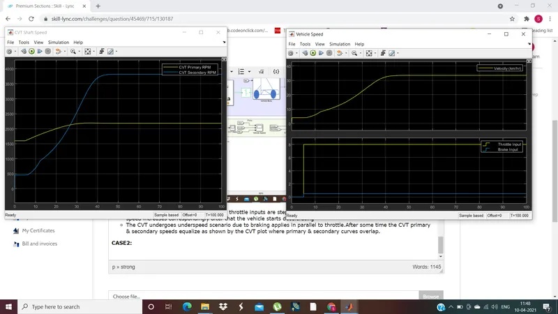
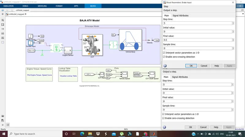
- In this case the braking force is very negligible compared to throttle power applied so the velocity of the vehicle is significant.
- The CVT experiences an overspeed condition after some point of time.
- In This case i have reduced the step time for the input signals & also change the initial & final values of braking force & throttle.
4. cvtModel_dashboard_mapped
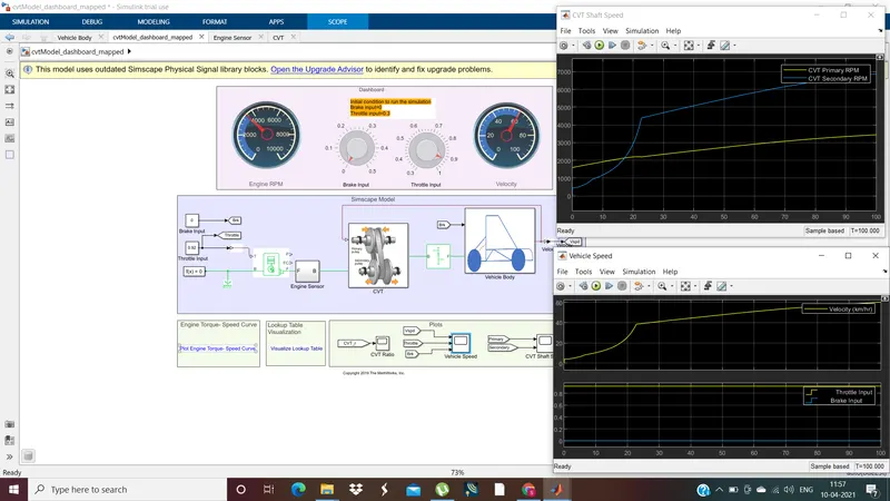
- The characteristics and behaviour of this model can be explained the same way as the above models
- Due to no braking force & significant throttle power the vehicle speed increases steadily & CVT experiences overspeed in a less amount of time
5. cvtModel_cvtratio_rpm:
CASE1:
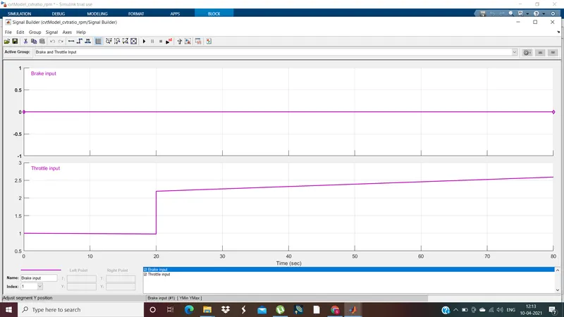
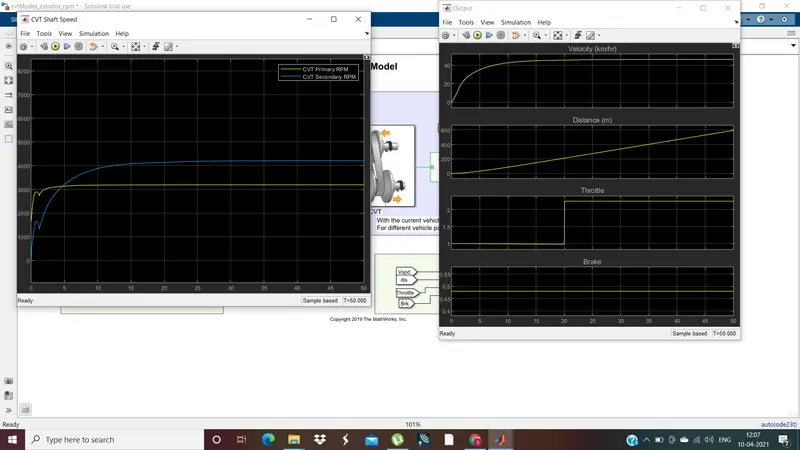
- The output characteristics & behaviour of the model can be explained with the same concept as for the above models discussed.
CASE2:
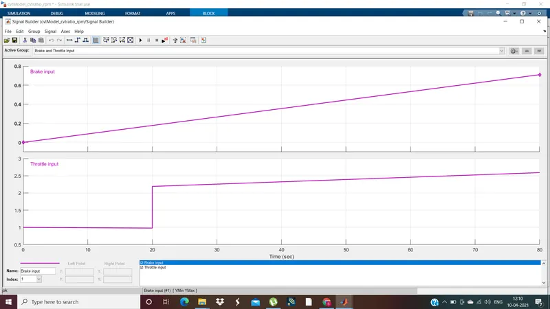
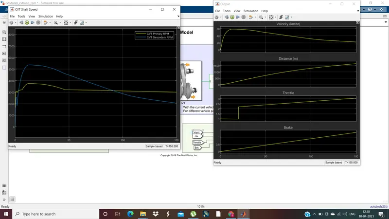
- The output characteristics & behaviour of the model can be explained with the same concept as for the above models discussed.
- Due to steadily increasing braking force along with increasing throttle there is less acceleration of vehicle & vehicle soon decelerates.
- The CVT experiences the underspeed condition faster in this case due to more significant braking force.
THANK YOU