Week 8 Challenge
8.
Load the UC parameter file. Complete the Ultracapacitor model. Set simulation stop time to 598 sec.
The model output should give, current, SOC and Voltage as output
Ans.
Ultracapacitor specifications are taken from [2] for Maxwell BCAP 3000 capacitor. They are as given below.
Rated Voltage = 2.7 V
Rated current = 400 A
Capacitance = 3000F
Lump resistance (ESR) = .29 m ohms
Max. power requirement from the capacitor = 82.855 kW
Considering all capacitors in UC pack to be in series,
UC pack min. voltage requirement = 83kW/400A = 207.5 V
Number of UCs required in the pack = 207.5V / 2.7V = 76.8V ~ 77
All these values are stored as variables to the .mat file. This file is loaded into the workspace before running the simulation.
Working –
Ultracapacitor power demand is provided through a signal builder block that has power values in watts for 598 sec. First, current is calculated with the equation shown below.
 (1)
(1)
A subsystem is created for current calculation which takes power demand (PUC) and SoC as input and outputs the ultracapacitor current(I). Here the input SoC is taken from output of the subsystem that calculates SoC with a memory block in between. Initial SoC is assumed to be 100%. Current values are calculated only when there is power demand from ultracapacitor (i.e., when power>0).
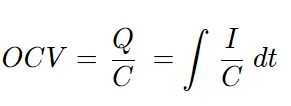
A subsystem is created for calculating the ultra-capacitor open circuit voltage as per the below equation. Input to the subsystem is current calculated before.
 (2)
(2)
A subsystem is created for calculating the charge built up inside ultracapacitor. The equation is as shown below-
Q = C*OCV (3)
Here, the OCV value is obtained from equation (2)
Finally, SoC is calculated as per the below equation-
SoC = Initial SOC + ∫ (I∗η) / Q dt (4)
The I and Q values obtained from (1) and (3) are given as input to this subsystem and output is the SoC which is fed back to the subsystem for I calculation, making it a feedback loop.
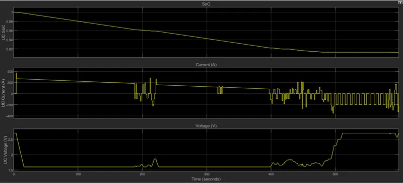
I, SoC and V values are plotted in scope. SoC reduces from 100 to 91% over the period of 598 seconds. Initially, current values are positive, meaning ultracapacitor is discharging the power. After 400 seconds, there is lot of braking, hence negative current. Over the period of negative currents/charging currents, it can be seen that SoC doesn’t reduce but stays constant and there is improvement in voltage values as well.
Ref-
[2] https://www.maxwell.com/images/documents/k2series_ds_10153704.pdf