Week 4 Challenge
1.
Nernst equation derivation-
Ref: http://courses.washington.edu/mengr430/au07/handouts/nernst.pdf
A fuel cell reaction with two reactants and two products can be represented as follows-
αA + βB `rarr` cC + δD (1)
Consider the representation of a fuel cell system that makes use of this reaction-
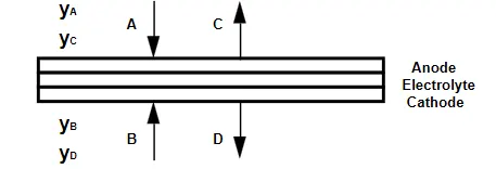
At anode, A is consumed and C is produced.
At cathode, B is consumed and D is produced.
The local ideal cell voltage will be determined by the infinitesimal amount of reversible work produced for an infinitesimal amount of reagents consumed. This differential reversible work in a thermodynamic system with constant temperature and pressure can be represented using Gibb's energy equation-
dW = dh - Tds (2)
where
dh - differential enthalpy
T - temperature
ds - differential entropy
Expanding the equation gives-
dW = hAdnA+ hBdnB+ hCdnC+ hDdnD – T[sAdnA+ sBdnB+ sCdnC+ sDdnD] (3)
Relation between differential change in the stochiometry of reactants and products as per equation (1) shown below-
dnA/α = dnB/β = -dnC/c = -dnD/δ = dn (4)
here, dn represents the differential change in the reaction stochiometry
Substituting dn for all the individual dni-
dW/dn = α.hA + β.hB - c.hC - δ.hD – T[α.sA + β.sB - c.sC - δ.sD] (5)
Enthalpy expansion-
hA = `h^0`f,A + (hT - h298)A
Entropy expansion-
sA = `s^0`A - R ln(PA/P0)
Substituting this into equation 5, and collecting the partial pressure terms together gives
dW/dn = α.hA + β.hB - c.hC - δ.hD – T(α.`s^0`A + β.`s^0`B - c.`s^0`C - δ.`s^0`D) + RT ln ( `P^α`A `P^β`B /`P^c`C `P^δ`D`P^(α + β - c - δ)`0) (6)
Since the partial pressures are in atmospheres, and P0 is always one atmosphere
Dividing the equation by nF,
where,
n = number of electrons moved per unit stoichiometry(equation 1),
F = Faraday's constant,
then the differential work terms become local voltages.
Thus, the final Nernst equation is-
E0 = ET,1 atm + `frac{RT}{nF}` ln (`P^α`A `P^β`B / `P^c`C `P^δ`D`P^(α + β - c - δ)`0)
or in other words,
ET = ET,1 atm + `frac{RT}{nF}` ln (`P^x`reactants / `P^y`products) (7)
where
ET = open circuit voltage
ET,1 atm = standard potential of the reaction
F = Faraday’s number, 96487 C/equiv
R = universal gas constant, 8.314 J/ °K-mol
T = absolute temperature of cell, °K
Preactants, Pproducts = partial pressures or activity of the species involved
n = the number of electrons involved (equiv/mol)
x, y = stoichiometric coefficients
Nernst equation for fuel cell-
Ref: http://users.encs.concordia.ca/~pillay/fuel-cells.html
The open circuit voltage ET of the cell by convention is measured as the difference between the potential drop at the cathode anD the potential drop at the anode at some temperature T.
 (8)
(8)
The Nernst equation for the overall cell reaction of the PEM fuel cell can be obtained by taking the Nernst equation in (7) for oxygen and hydrogen reaction that occurs at the cathode and anode of a PEM fuel cell and subtracting it as per (8)
Anode: 2 H2 `rarr` 4`H^+` + 4e-

Cathode: O2 + 4`H^+` + 4e- `rarr` 2H2O

Overall: 2H2(g) + O2(g) `rarr` 2H2O
From (8)

Thus, Nernst equation for a hydrogen fuel cell is -

Parameters affecting the Fuel cell reaction-
Reference: https://www1.eere.energy.gov/hydrogenandfuelcells/tech_validation/pdfs/fcm04r0.pdf
- Temperature - Higher temperatures improve mass transfer within the fuel cells and results in a net decrease in cell resistance (as the temperature increases, the electronic conduction in metals decreases but the ionic con-duction in the electrolyte increases). Together, these effects improve the reaction rate
- Partial pressure of gases - The rate of the chemical reaction is proportional to the partial pressures of the hydrogen and the oxygen. This is because higher pressures help to force the hydrogen and oxygen into contact with the electrolyte. Although an increase in pressure promotes the electro-chemical reaction, it introduces other problems. Fuel cell stack flow field plates work better at low pressure since they exhibit smaller flow-induced pressure losses. Fuel cell seals operate under additional stress. Additional air compression is required, which absorbs more of the gross power. Other system components must be re-designed accordingly; some components must increase in size and cost. Ultimately, increases in pressure achieve diminishing returns when considering both stack efficiency and overall system consequences.
- Stochiometry effects - Stoichiometry refers to the ratio of the amount of gas present relative to the amount of that gas that is needed to exactly complete the reaction. Higher stoichiometry increases the chance that sufficient numbers of hydrogen and oxygen molecules interact with the electrolyte. Insufficient stoichiometry deprives the fuel cell stack of sufficient reactants and may cause permanent damage.
- Humidity - Insufficient humidification water dehydrates the membrane and can lead to cracks or holes in the membrane. This results in a chemical short circuit, local gas mixing, hot spots, and the possibility of fire. Conversely, excess humidification water leads to condensa-tion and flooding within the flow field plates. This can result in a phenomenon known as cell reversal where the affected cells produce a zero or negative voltage. If a large enough negative voltage occurs, the affected fuel cells start to act like an electrolyzer. This produces a lot of heat and can potentially destroy the cell.
2.
The points-
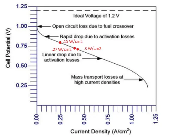
.15W/cm2, .27 W/cm2, .3 W/cm2 are highlighted on the plot attached.
Power/cm2 = Cell voltage * Current/cm2
the points can be plotted using this calculation.
3.
.27 W/cm2 is the best point to operate the fuel cell as it belongs to the sweet spot where
It is ideal to operate at a point that gives efficiency as well as power.
As we move towards the left of graph, full efficiency increases since the cell output voltage increases. This means a lower current consumption. This indeed saves the amount of fuel consumed. But power output will be less here. As we move towards right, power output will also increase. Thus, a balance need to be maintained where we get good fuel efficiency with max. power. At the same time, going more towards right will decrease the cell output voltage which is not favourable since the DC-DC converters connected to the fuel cell need a minimum level of operational voltage. Thus the point with .27 W/cm2 provides this.