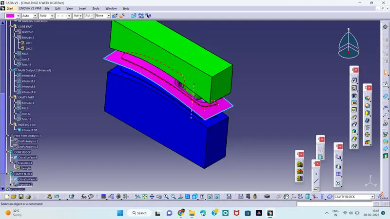
Week 8 - Challenge 6 - Core & Cavity Design
CHALLENGE 6
CORE AND CAVITY DESIGN
AIM: To design the core and cavity blocks for the switch bezel.
From the last challenge of switch bezel we can design
- TOOING AXIS
- DRAFT ANALYSIS
- PARTING SURFACE
- PARTING LINE
- CORE BLOCK
- CAVITY BLOCK
And in the last publish them in the tree structure.
TOOLING AXIS:
Tooling axis is the direction in which the core and cavity opens in the tooling direction.
- Open the switch bezel close surface of last which we create in the earlier challenge.
- Extract one flat surface then create a point at the middle of the extracted surface and insert an axis system.
- Intersect the object in ZY direction and create a lines at both the ends of the intersection and create a bisection line between the created lines.
- Again intersect the object in ZX direction and create a line at cut section end and then create a bisecting line using this line first bisecting line make an angle 3 degrees
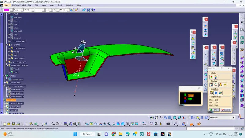
- when making an angle with 3 deg it shows some red colours in the draft analysis and it is not suitable for the tooling axis. Again go with a 6 deg
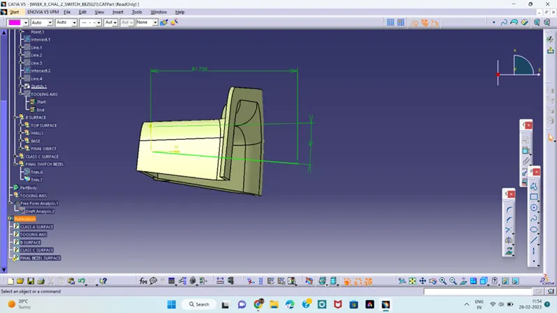
- Next is to analyse the draft and check if is the correct tooling direction or not.
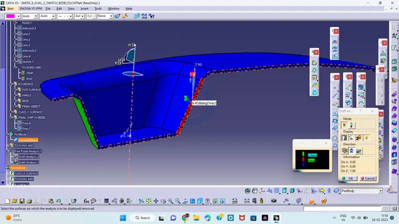
- This the correct tooling direction but again it shows some red colour at the side edge surface and to correct for this change the angle at some inclination at 2.9 deg .
- Now the Tooling axis for the switch bezel component is created.
- Next is to perform the draft analysis.
DRAFT ANALYSIS;
Draft analysis technique is used to analyse the whether our part model created in CAD is manufacturable based the draft condition applied.
- First go with the draft analysis command and place the compass at the tooling axis and click the compass option in the draft analysis table.
- Click on the component and some colour changes in the component.
- Top side of the object is in green colour which means this is the core object.
- Bottom side of the object is in blue colour which means this is the cavity object
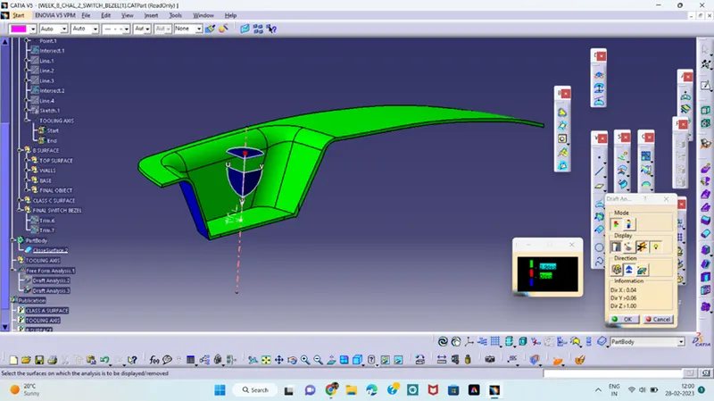
This is the final draft analysis for the switch bezel component and next is to create a parting surface of the component.
PARTING SURFACE;
Parting surface generally, injection mold has two components: the movable halve and the fixed halve, during injection molding process these two halves are pressed tightly and form a sealed hallow to avoid the melt flow leakage and maintain certain holding pressure, the pressed surface are called parting suface, usually the parting surface is the biggest projection outline of the part.
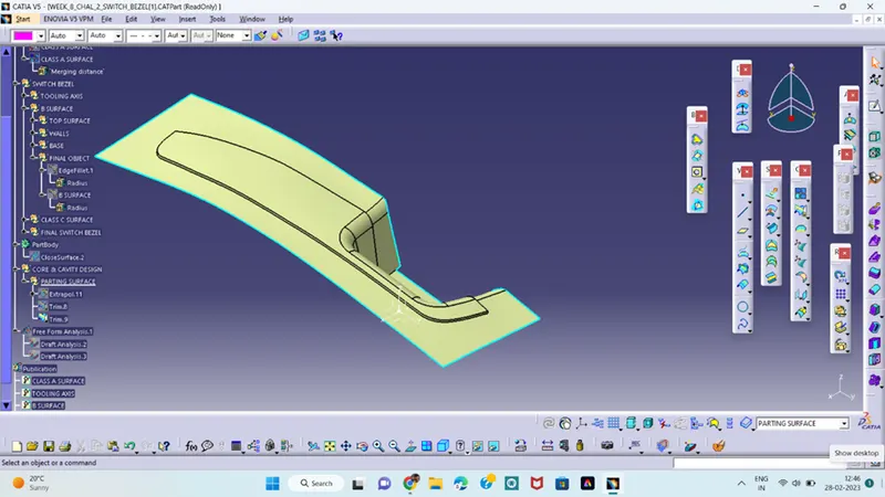
This Is the parting surface of the object which we create.
PARTING LINE:
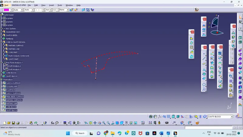
It is the line in which the two halves are divided in the mold. It is the intersection line between the core and cavity blocks. Or
The outline of the core and cavity blocks of the mould.
CORE BLOCK:
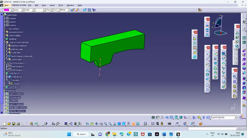
It is the raised part of the mould of the plastic object.
CAVITY BLOCK:
It is the recessed part of the mould in the plastic component.
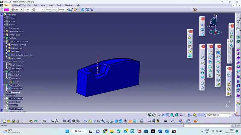
Final design of core and cavity