Week 8 - Challenge 6 - Core & Cavity Design
REPORT:
AIM: to create the coreblock and cavity block for the switch bezel.
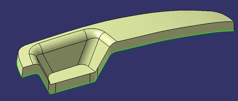
PROCEDURE:first we have to open the switch bezel cat part and then we have extapolate the class A surface to a maximum length for example 15 mm.after extapolating the class A surafce we have to un hide the join of class A and class C and then we have to trim the extapolation of class A with that join.the output will be as follows:
after gettting the output as above picture we have to create the PARTING SURFACE WITH COMPONENT AREA by unhiding the B surface and trimming it with the previous trim and the output will be as follows:
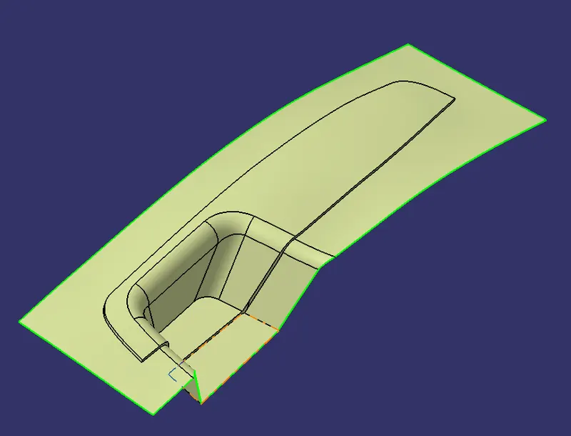
after gettting this we want to create a parting surface but for creating a parting surface we have a shortcut to create it we just have to use the split command to split the B surface with the component and the component and b surface got spliited in to two parts after we will hide the component and our out put will be as follows:
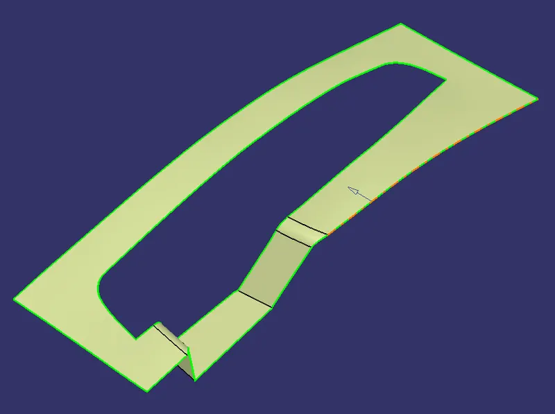
after getting the parting surface we have to cretae the core block design. To create the core block design we have to draw a rectangle which is outside the component and inside the split the below image will show the detail preview.
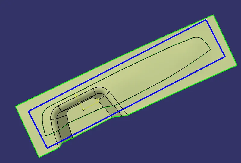
after creating the sketch we will extrude the sketch on both sides and then we will use the trim command to trim the lower surface and we will get the out put as follows:
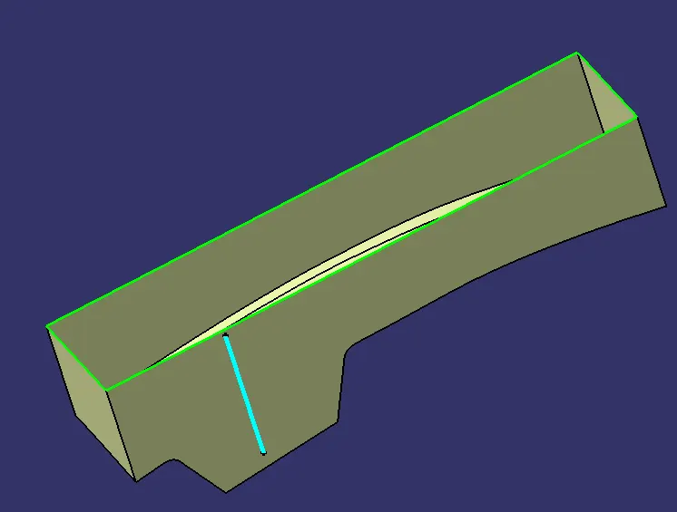
but after doing all this the top of the trim is open so we will use the fill command to fill the top open face and we will get the output as follows:
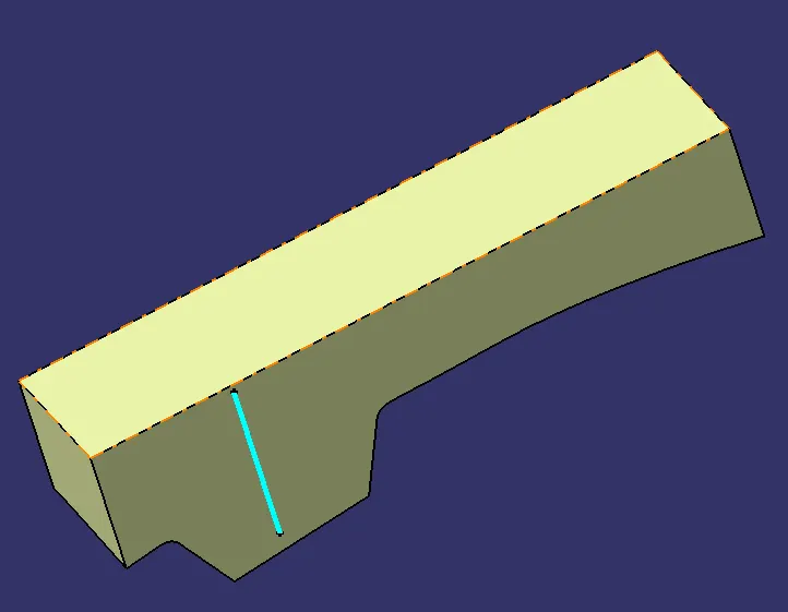
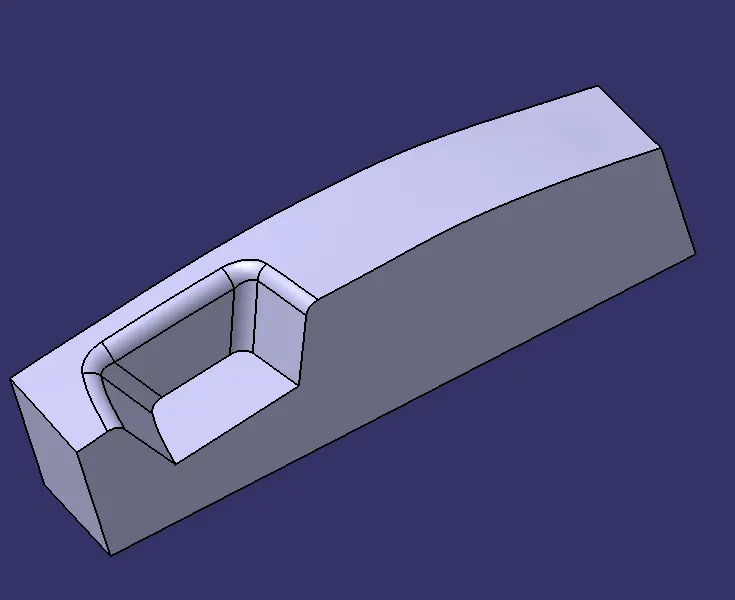
but after doin this also we get two surfaces that is trim and the fill so we use the join command to join them both.a fter joining we will take the intersection and see the component and after that we will make it as a solid component for making it as a solid component we will got part design workbench and use the close surface command to close the surface and we will get the out put as follows:
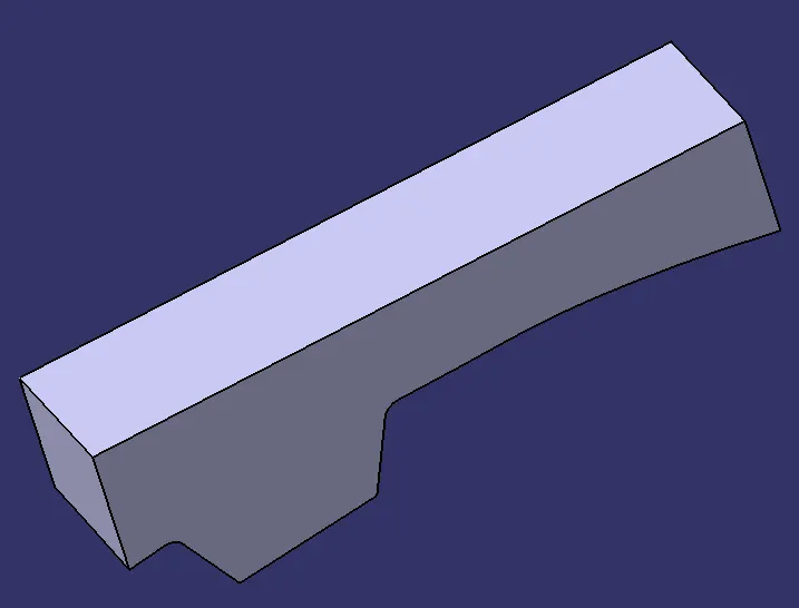
after getting the core part we will create the cavity part for creating the cavity part we will use the previous sketch and extrude it in both direction and we will trim by using trim command and we will trim the upper surafce and we will get the out put as follows:
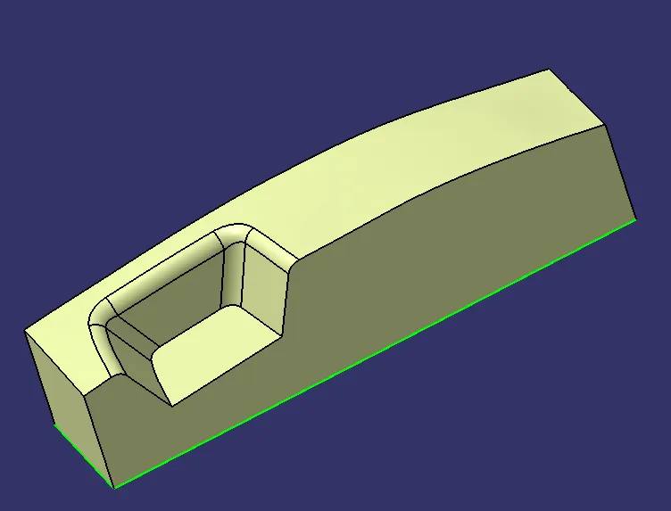
but here also we have the bottom surface open so we use the fill command to fill the bottom surface and then we join them both to make it as a single co ponent and then we will make it as a solid part by using close surface command in part work bench and we will get the output as follows:
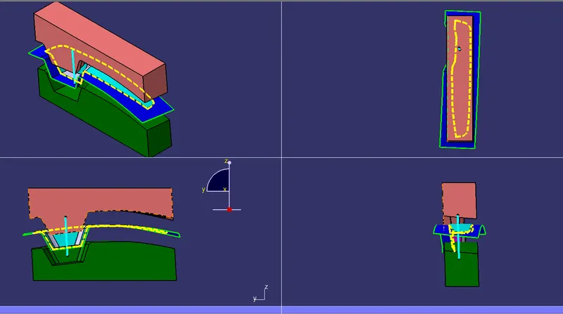
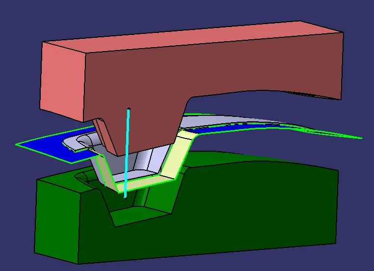
after getting both part as a solid we will unhide the component and the parting surface and we will bring everything to screen and we will use the translate command to translate the core and cavity part to a minimum distance and we will give some colour to it so that we can find everything easily and the output will be as follows:
CREATING DRAFTING ANALYSIS FOR CLASS A AND SOLID PART:
DRAFTING ANALYSIS FOR CLASS A:
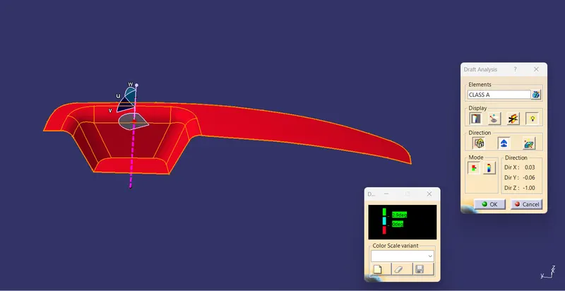
drafting analysis method:
go to insert>analysis>feature draft analysis
After clicking on draft analysis tool click the compost tool and drag it to the tooling axis and lock the compass after locking the compass click on the second option and display toolbar in the draft analysis And then we have to check the drafting angle the minimum drafting angle should be 3 degree.
DRAFTING ANALYSIS FOR SOLID PART:
drafting analysis method:
go to insert>anlysis>feature draft analysis
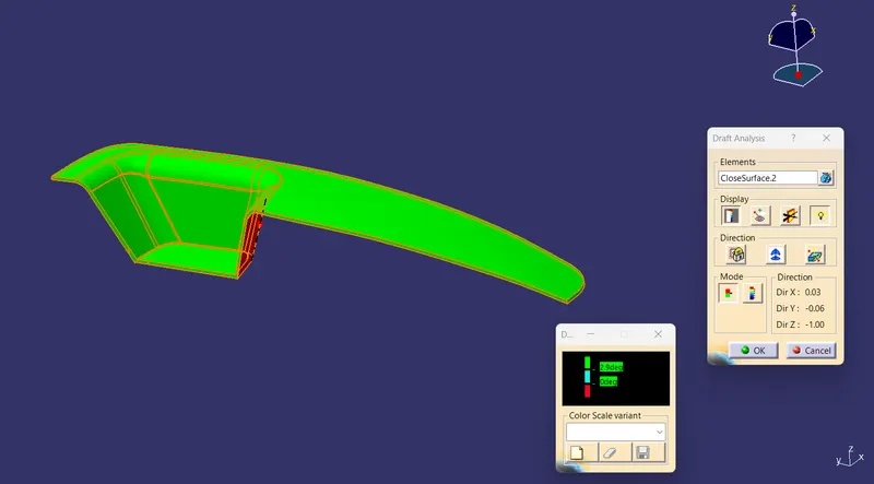
Using the draft analysis command and selecting the composs tool in the direction toolbar and dragging it to the tooling axis and then locking it there and using the compass and checking the drafting angles the drafting angle should be maximum 3 degree and it should not increase more than that after placing the compass we get a red dot on the cursor by clicking the red dot on the component the color of the component will change the top becomes the green and the bottom becomes the red color.
we will get the output in two colors One is green color on the top and the red the color in the bottom which means the green color is 3 degree and the red color is saying that the draft is less than zero degree and the red draft was not original before it was blue color But for our reference I have changed it to the red color so that we can find it easily that it has a negative value.
after finishing the checking of drafting analysis we have to hide the drafting analysis And then our component is ready for manufacture.
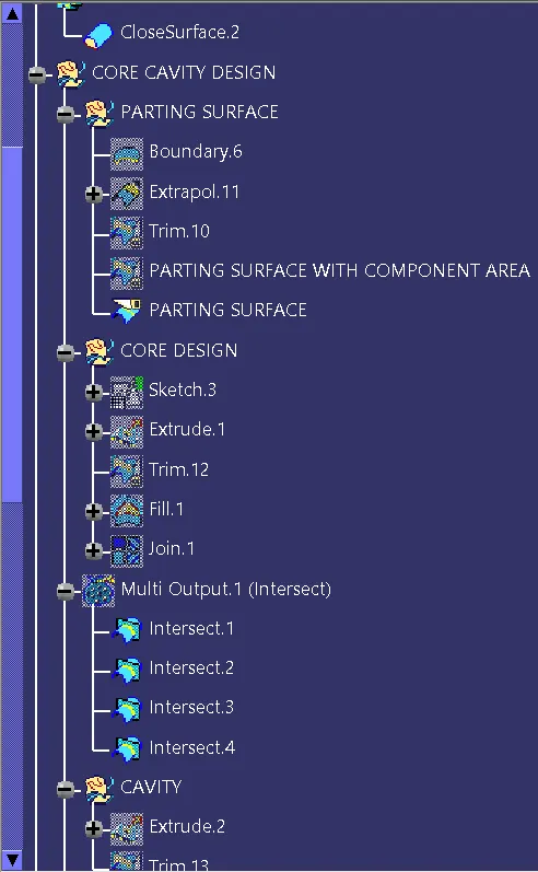
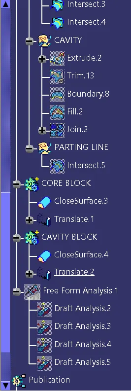
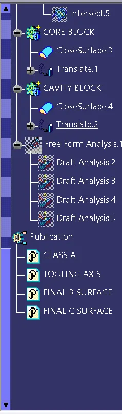
tree structure:
diffrent views: