Week 8 - Challenge 6 - Core & Cavity Design
Report on the Creation of the Core and cavity blocks for the switch bezel.
Steps involved in the procedure:
- Tooling Axis creation
- Draft analysis for created tooling Axis and Model
- Core and cavity design
Description:-
The given input for the exercise is the Class A surface of the Switch Bezel. The job of the product designer is to create the Class B and C surface keeping all the design principles and mold aspects in check using the Class A surface in mind.
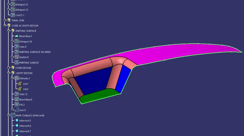
Class B surface is the invisible Surface. It mostly doesn't have textures. It needs to be created according to the class-A surface. It contains all features(Rib, boss, snap, etc) on the B-side surface only.
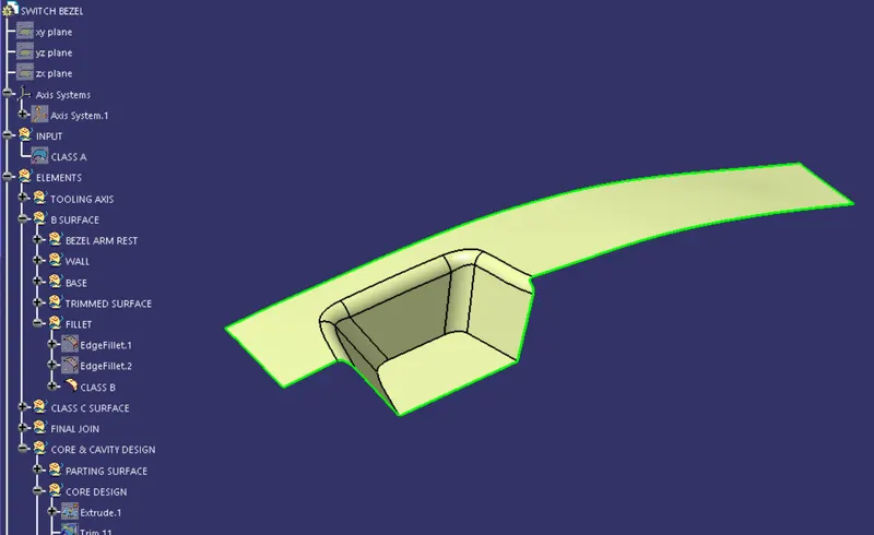
Class C is constructed along the boundary of CLASS A surface using the swept command with respect to the tooling axis direction with a draft angle of 3 degrees.
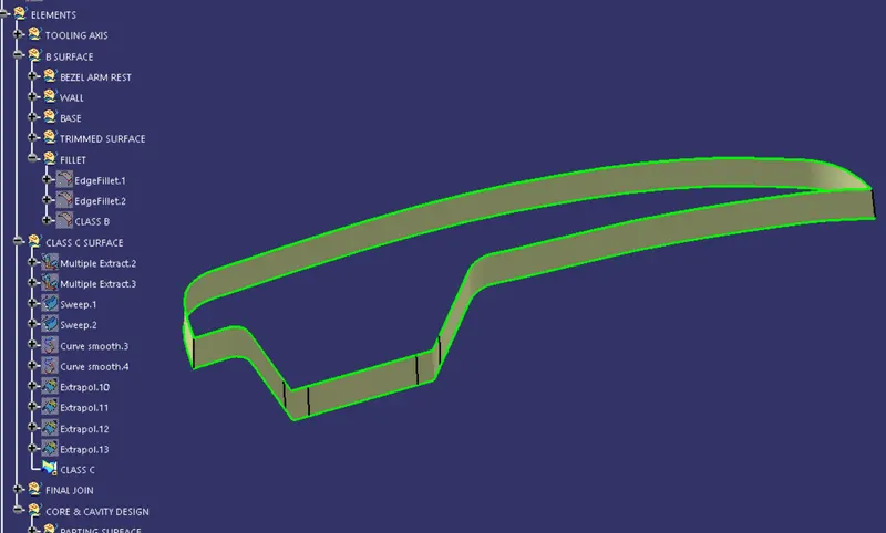
By using the Join function to join the Class A&C surface and by Trimming the join with the Class B surface we can obtain the model required. And it is the model around which the Parting surface and parting line is been made and is the actual output of the mold.
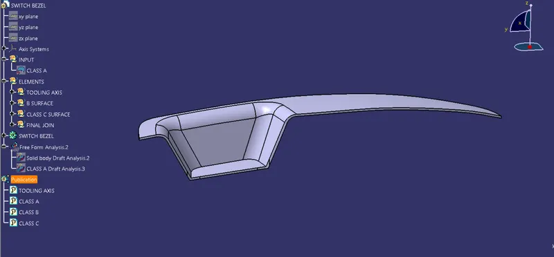
- Tooling Axis creation
For any part to be manufactured, it involves the feasibility analysis for a Class A surface of the component, whether it be Sheet Metal or Plastic. To evaluate the manufacturability of the components, it must go through design checks and Draft Analysis which is one of the significant steps incorporated into these evaluations. For any component, while manufacturing using Core and Cavity it is rectified whether it is ejected properly which shouldn't have a straight 90 degree to its base surface. For this purpose, the draft angle is given to the component to get easy ejection for the tool, generally, for plastic parts, a 3-degree angle is given. However, before initiating the Draft analysis the tooling direction is first visually analyzed to get the representation of how the part is going to be manufactured or rather in which suitable direction. While skimming through the body the surfaces which are parallel or closed to the parallel are most likely to disrupt the manufacturing. Apparently, which can be avoided if gone through a draft analysis. The creation of the Tooling axis is the way to verify the draft angle, to create a tooling axis there are two methods depending upon the geometry one can use either one of them
One method is by using the flat or the hole geometry to create the tooling axis is the most convenient although, depending upon the geometry it can be initiated.The second method is by using Bisecting method, to instigate the process similarly having a closed geometry such as a circle or flat surface which will be handy to create a dummy tooling axis, further using the intersection tool in the tool direction plane as a guide for the parallel geometries can be created and using the two of the line the axis can be created using the bisecting option which will be the actual tooling axis for the body to be manufactured in that direction
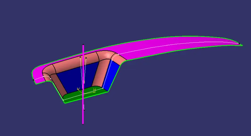
- Draft analysis for class A and the Model
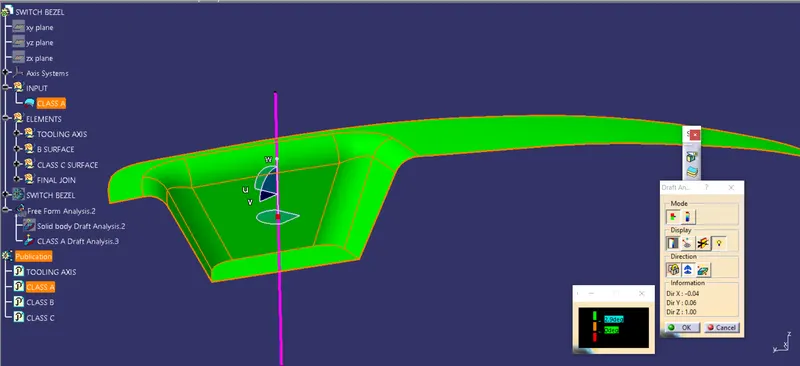
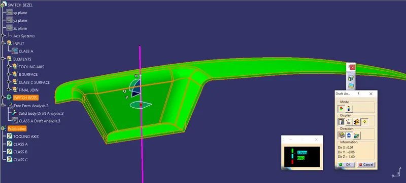
Furthermore, Draft Analysis can be done using the tooling axis that is created, on defining the part body and selecting the draft analysis option selection of direction using the compass and redirecting to the tooling axis will be the reference for the draft analysis. On selecting the surface the surface will depict the output for the draft angels using a colored scale. By default for a draft angle of 3 degrees or more, it will show green, for 0 degrees it will show red and for the negative draft angle, it will show blue. Additionally, one can use the other mode besides the default mode which is much more detailed with various draft angle ranges which can be used for the desired surface for draft analysis.
For this particular exercise, the solid model has been draft analyzed using some modifications such as changing the default set of colors to different ones to allocate variations quickly, changing the draft angle, and getting the desired output with all the possible surfaces which may cause problems in manufacturing. By changing the angles between the supporting and the bisecting line a stable output is obtained which is directly reflected in the final output.
Core and cavity design:
The Mould Core & Cavity are the shaped sections in either half of the mold tool which give the plastic product its final shape. The hot molten material is injected into the core & cavity and then sets hard into shape. The design of the core & cavity is essential in the correct formation of the product. The sequence of events during the injection mold of a plastic part is called the injection molding cycle. The cycle begins when the mold closes, followed by the injection of the polymer into the mold cavity. A core is usually made of the best quality sand and is placed into the desired position in the mold cavity. Core prints are added to both sides of the pattern to create impressions that allow the core to be supported and held at both ends.
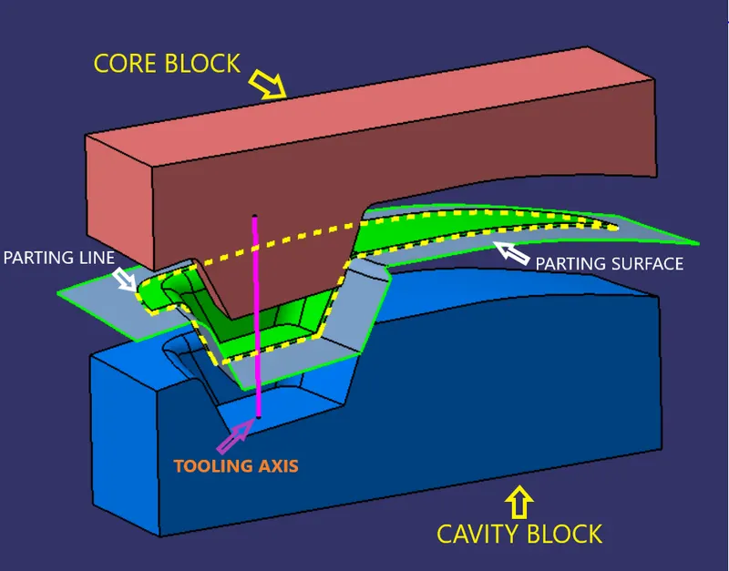
Generally, injection mold has two major components: the movable half and the fixed half, during the injection molding process, these two halves are pressed tightly from a sealed hollow to avoid melt flow leakage and maintain certain holding pressure, the pressed surface is called parting surface, usually parting surface is the biggest projection outline of the part.
Principles to follow while designing the Parting surface.
- The injection mold should be designed as simply as possible
- Avoid or reduce side parting as much as possible to reduce the complexity of mold making.
- De-molding should be easy, the plastic component should be ejected using the ejector pins while it has stayed on the fixed half to avoid side de-molding
- The dimensional accuracy of the molded part should be great and checking how can we reduce manufacturing and assembly errors.
- appearance requirement of the molded parts should be fulfilled, Flash or mismatch occurs usually on parting surface, so the parting surface should not be designed on any high-quality requirement surfaces
- Good enough venting should be there, it is advantageous for filling and venting if the parting surface is placed at the end of the mold flow
Core design
A core is one part of the mold and is half of the molded part. these core and cavity combine to form a mold. the plastic is injected into these molds to get a plastic part.
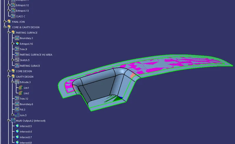
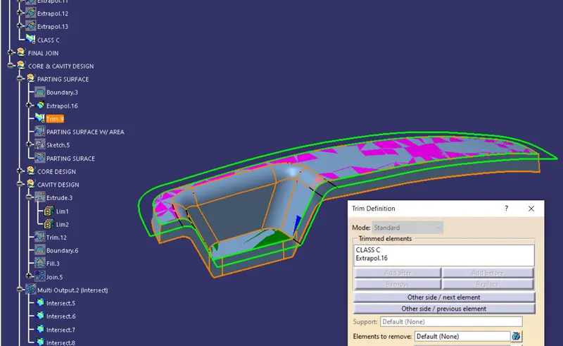
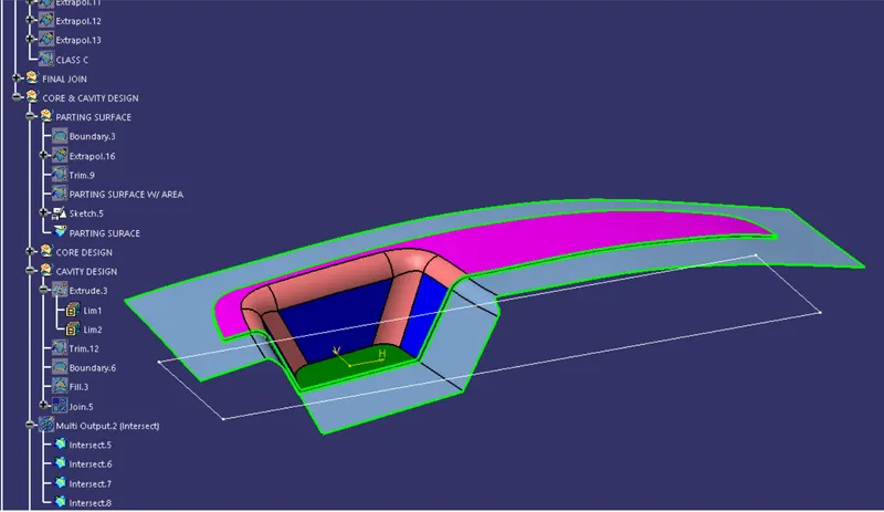
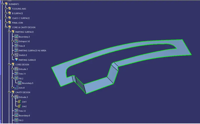
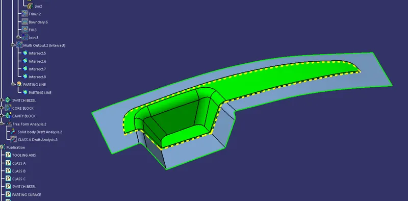
the line of separation between where two halves of a mold meet is called the Parting Line.
To make the core block a defined rectangular geometry can be introduced to make a uniform solid
Extruding and Trimming can give out a closed blocked with one open side which can be filled using the fill command and Join together with the join Feature
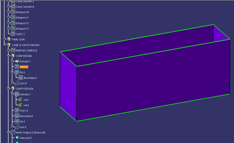
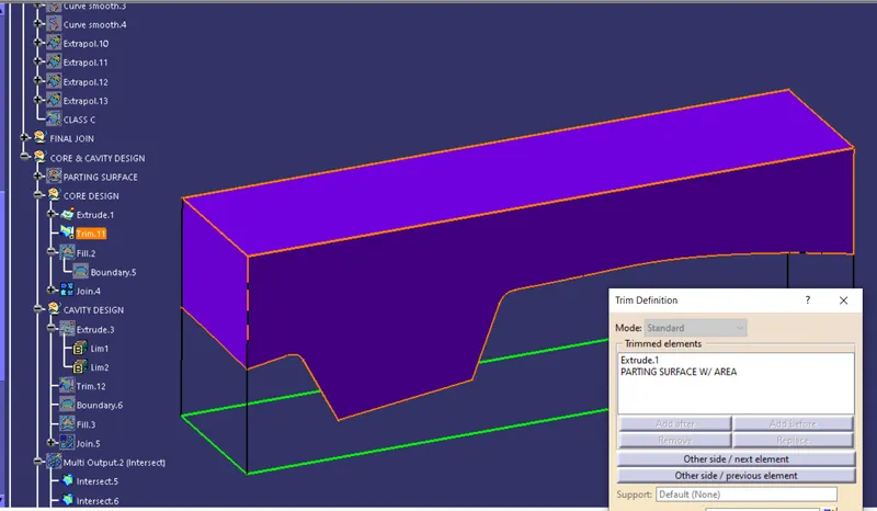
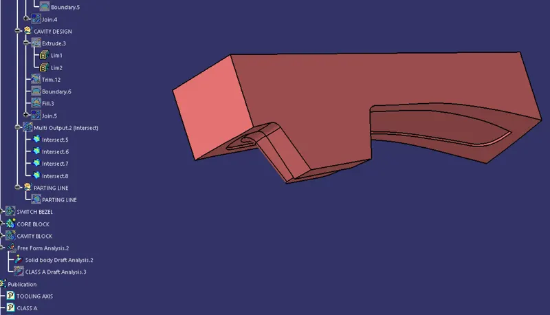
Similarly,
A cavity block can be designed. It is a hollow form typically made from stainless steel that has plastic injected into it to manufacture a plastic part. The plastic is inserted into the mold cavity, which is a hole in the mold shaped like the desired part.
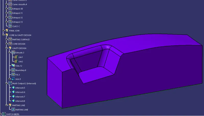
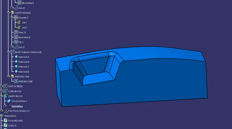
With the use of the Intersection command, we can verify and examine the boundaries altogether.
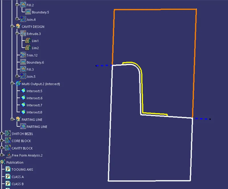
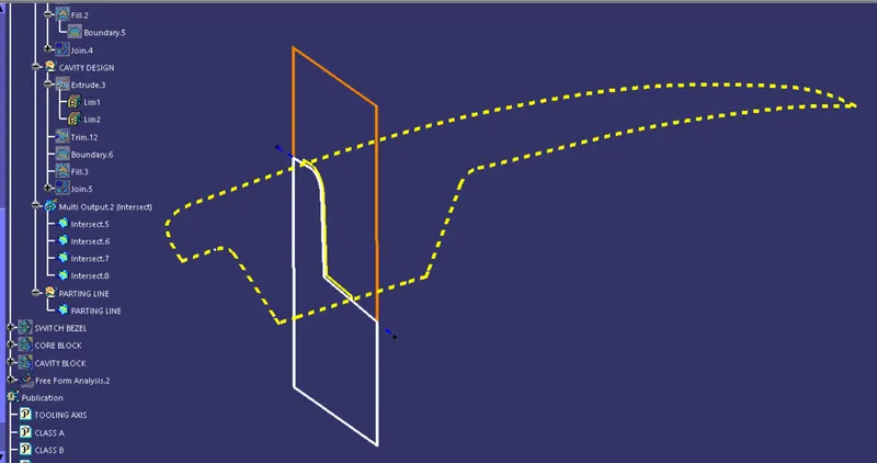
Finally, the Core and Cavity block is obtained. And the assembly representation of it is shown bellow
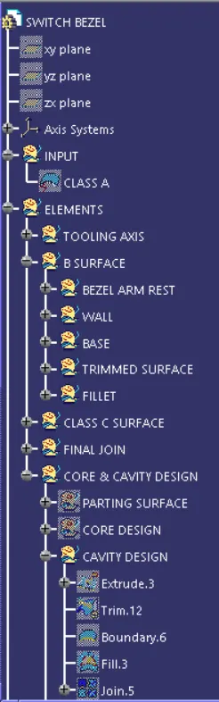
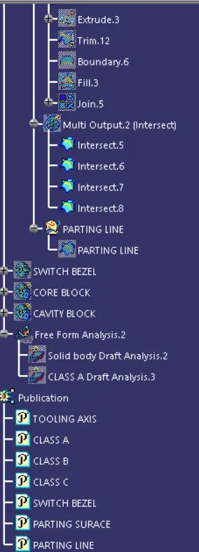
Tree structure:-