Week 8 - Challenge 3 - Coin Holder Design
REPORT ON MAKING OF COIN HOLDER WITH THE USE OF GIVEN INPUT CLASS A SURFACE AND PERFORMING DRAFT ANALYSIS ON BOTH THE MODEL AS WELL AS ON THE CLASS A SURFACE WITH DETAILED OVERVIEW ON THE SURFACE MODELING.
STEPS INVOLVED IN THE PROCEDURE:-
1. INSPECTION AND APPLICATION OF THE TOOLING AXIS.
2. REFERENCING OF SURFACES FOR THE B SURFACE.
3. MAKING OF THE C SURFACE.
4. JOINING AND MAKING OF THE MODEL.
5. DRAFT ANALYSIS OF THE MODEL.
- INSPECTION AND APPLICATION OF THE TOOLING AXIS.
For the Inspection of the input surface, the Drafting analysis was performed on the class-A surface by using the Feature Draft Analysis command. Using this command, the compass was set on the main tooling axis and the Draft angle was changed to 3 degrees.
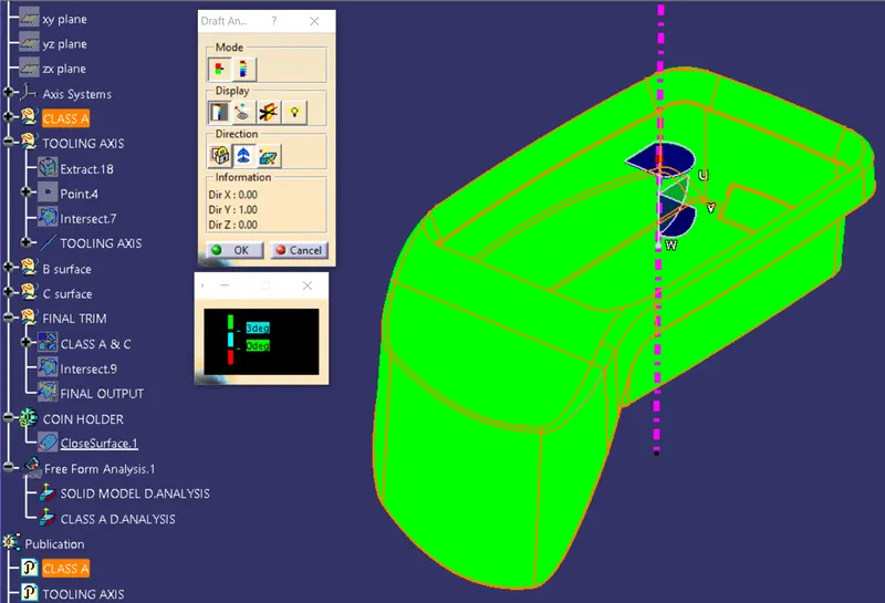
For any part to be manufactured, it involves the feasibility analysis for a Class A surface of the component, whether it be Sheet Metal or Plastic. To evaluate the manufacturability of the components, it must go through design checks and Draft Analysis which is one of the significant steps incorporated into these evaluations. For any component, while manufacturing using Core and Cavity it is rectified whether it is ejected properly which shouldn't have a straight 90 degree to its base surface. For this purpose, the draft angle is given to the component to get easy ejection for the tool, generally, for plastic parts, a 3-degree angle is given. However, before initiating the Draft analysis the tooling direction is first visually analyzed to get the representation of how the part is going to be manufactured or rather in which suitable direction. While skimming through the body the surfaces which are parallel or closed to the parallel are most likely to disrupt the manufacturing. Apparently, which can be avoided if gone through a draft analysis. The creation of the Tooling axis is the way to verify the draft angle, to create a tooling axis there are two methods depending upon the geometry one can use either one of them. One method is by using the flat or the hole geometry to create the tooling axis is the most convenient although, depending upon the geometry it can be initiated. The second method is by using Bisecting method, to instigate the process similarly having a closed geometry such as a circle or flat surface which will be handy to create a dummy tooling axis, further using the intersection tool in the tool direction plane as a guide for the parallel geometries can be created and using the two of the line the axis can be created using the bisecting option which will be the actual tooling axis for the body to be manufactured in that direction.
Although for this kind of model a direct method is approached, using a line at the mid-point of the base of the coin holder can be used as it is parallel to the walls of the class A surface
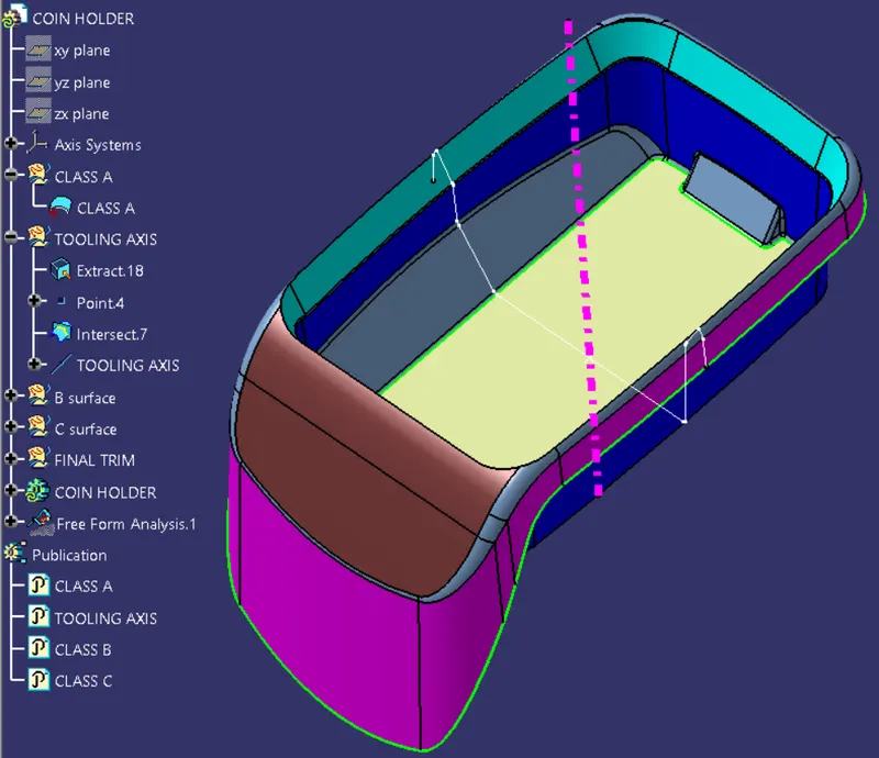
- REFERENCING OF SURFACES FOR THE B SURFACE.
Creation of the Class B surface can be then initiated by extraction of the surfaces from referencing the class A model with the use of the Extract command under Operations.
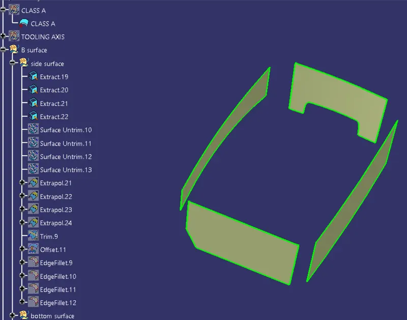
they are Untrimed and Extrapolated using the commands to enclose them into a single entity. Then Offsetted to 2.5mm given thickness. 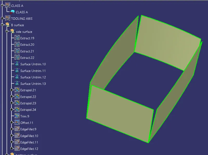
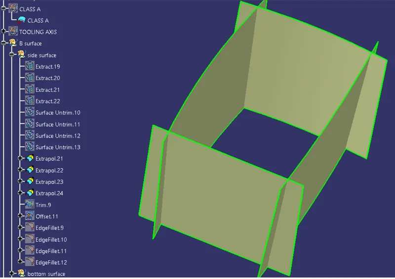
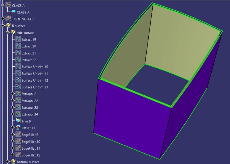
Further, by analysis giving the fillets inside with the thickness added.
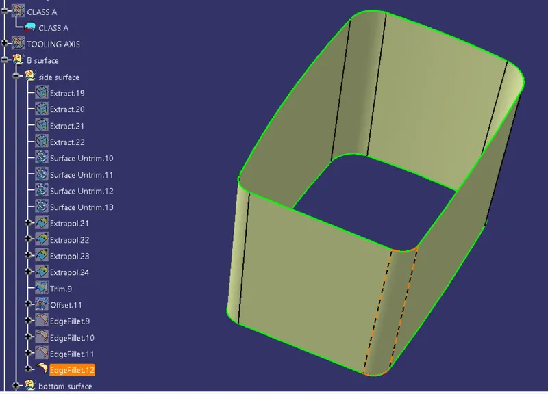
Similarly, applying the same principles of getting the surfaces for other walls such as the bottom and top walls.
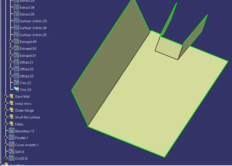
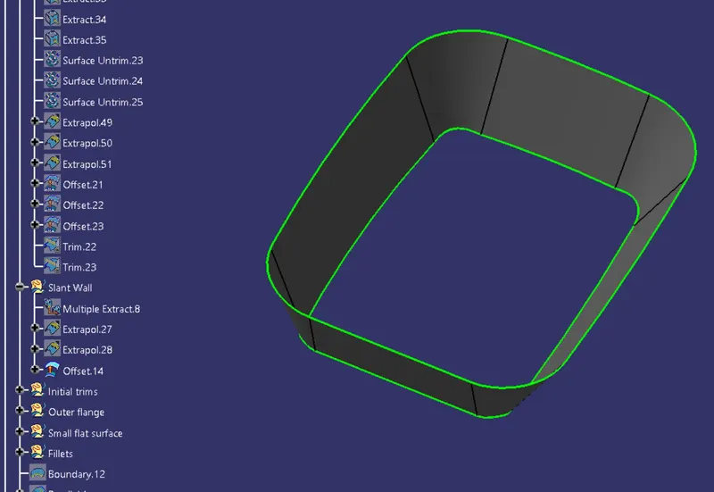
After getting all the surfaces trimming can be done to simplify it further.
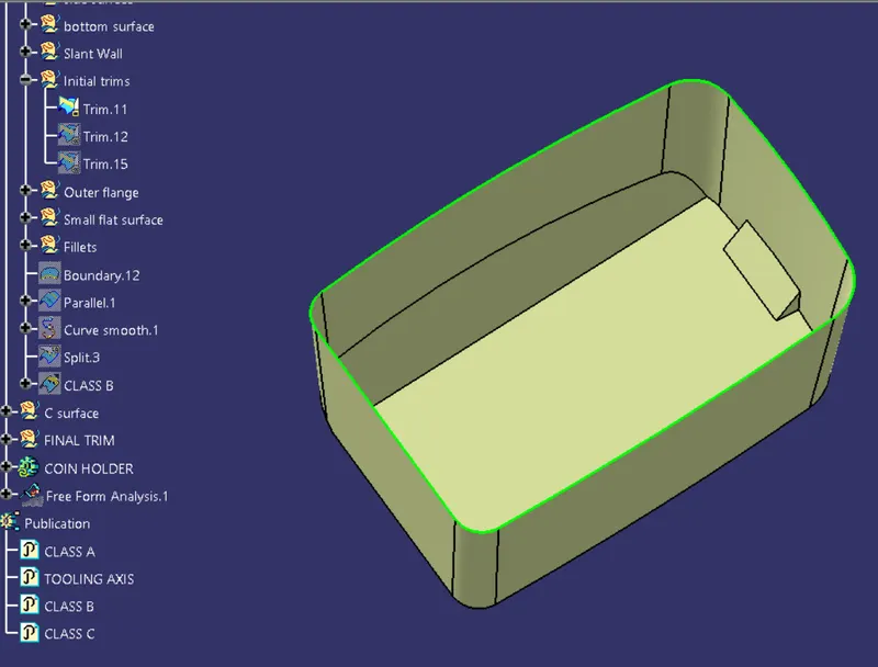
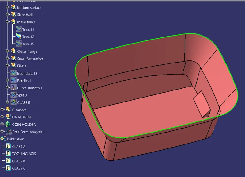
Similarly, for outer flange extraction > extrapolation > offsetting.
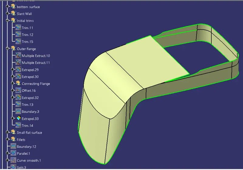
Trimming it with the previous output surface, giving fillets, and then extrapolating it a tad bit for avoiding any gap in further steps.
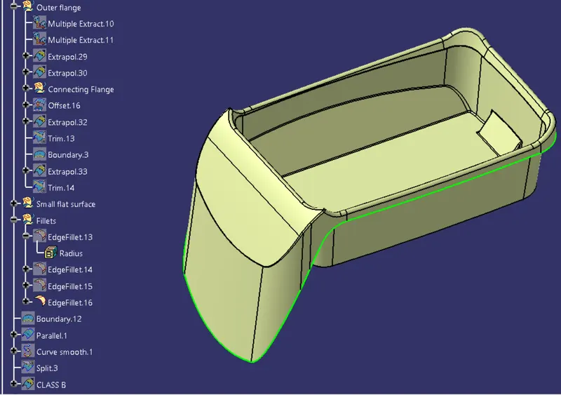
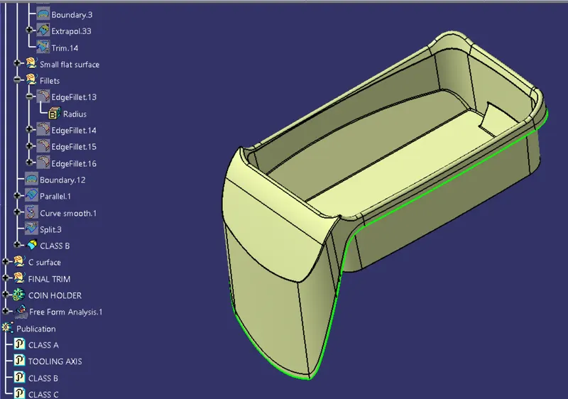
Class B surface is constructed
- MAKING OF THE C SURFACE.
By using the class A surface again to extract the guide surfaces to generate the Class C surface using the sweep command. With reference to the extracted surfaces as the guide with a specific angle of 90 degrees and desired length of more than the thickness, which can be trimmed off later can result in forming the Class C surface.
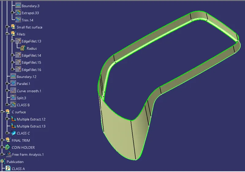
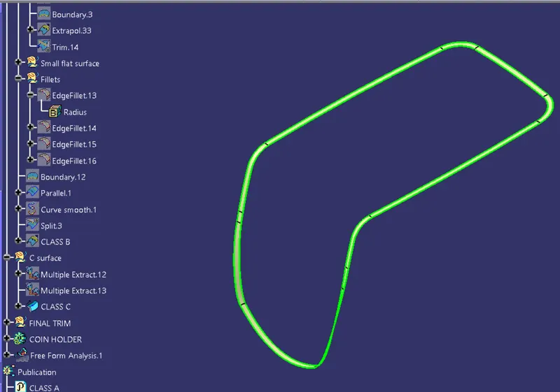
- JOINING AND MAKING OF THE MODEL.
Once Class C is acquired, the joining of the Class A and Class C surfaces can be done by using the JOIN command. Since the outer surface is formed now by trimming the class B surface can give the output model with the surface that is required with the overall thickness of 2.5mm.
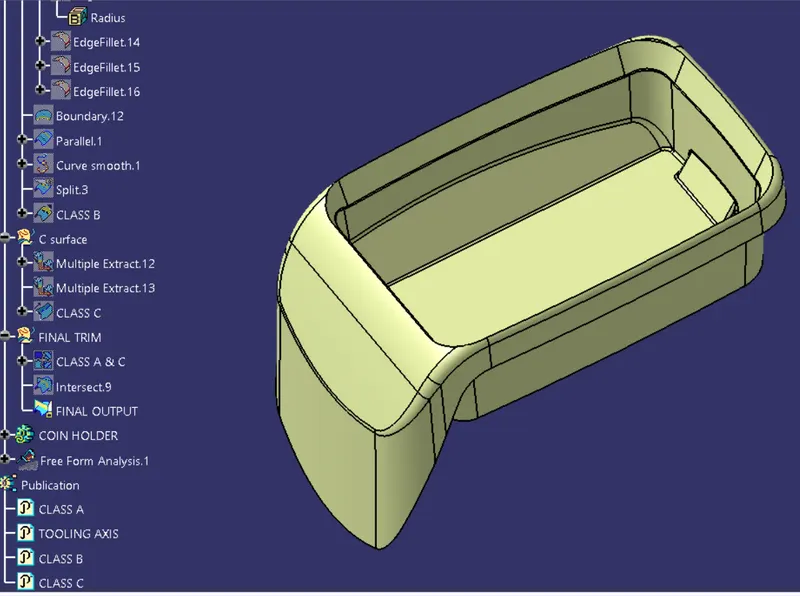
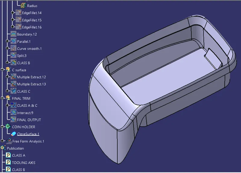
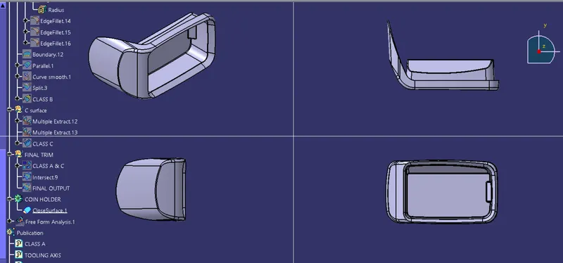
To make the SOLID model using the final output the Close Surface command is used from the part workbench.
- DRAFT ANALYSIS OF THE MODEL.
The final step of the procedure is to check the feasibility of the model using the Draft Analysis.
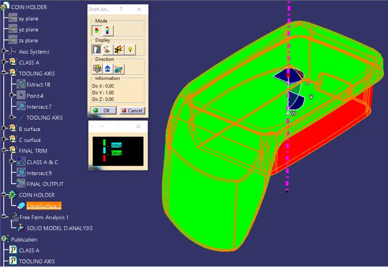
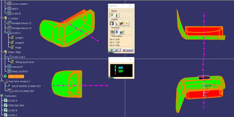
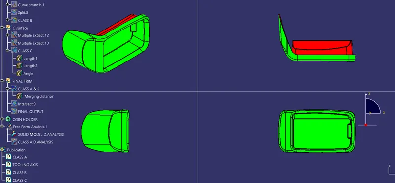
As the analysis depicts the results are positive with the reference to a 3-degree draft angle for the making and inspection for manufacturability of the coin holder with the help of class A surface. The procedure is done.