Week 8 - Challenge 6 - Core & Cavity Design
CORE AND CAVITY DESIGN OF THE SWITCH BEZEL
AIM: To create a switch bezel component using the class A surface there by generating the class B and C surfaces and doing the draft analysis with a proper tooling axis and thereby proceeding with CORE AND CAVITY DESIGN
with the guidance of the above mentioned surfaces and tooling axis
PROCEDURE:
- class A surface
- Tooling axis
- Draft analysis
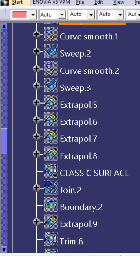
- Class B surface generation
- Class c surface generation
- switch bezel surface body
- Solid body
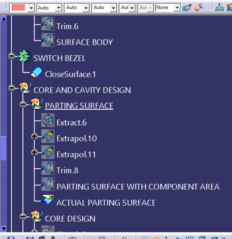
- Parting surface
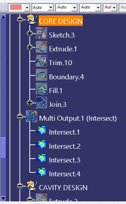
- core design
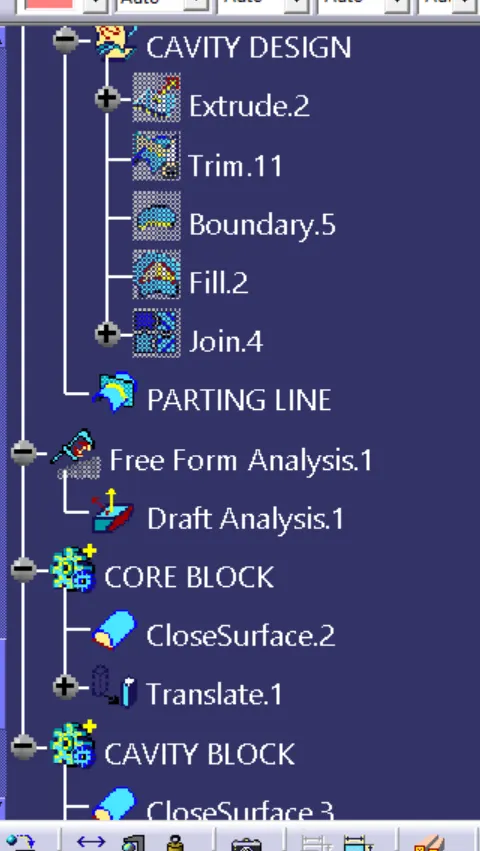
- Cavity design
- Parting Line
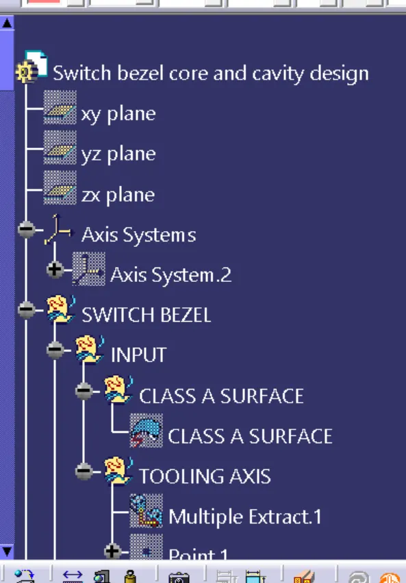
Class A surface:
Class A surface is the most asthetic surface with good finish appearance
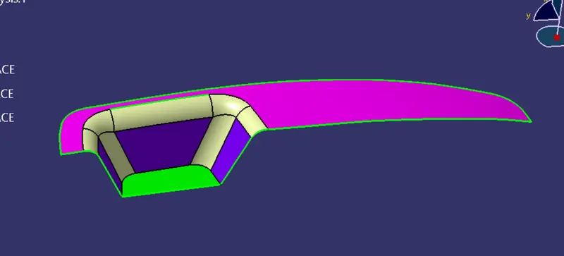
Distinguish the surfaces with different colours so that we can able to adopt the right surface for the tooling direction . Once the surfaces are distinguished use the right approach to find the tooling direction
Tooling axis:
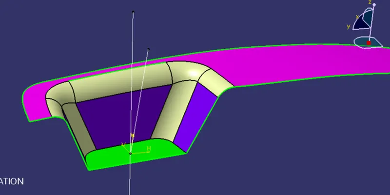
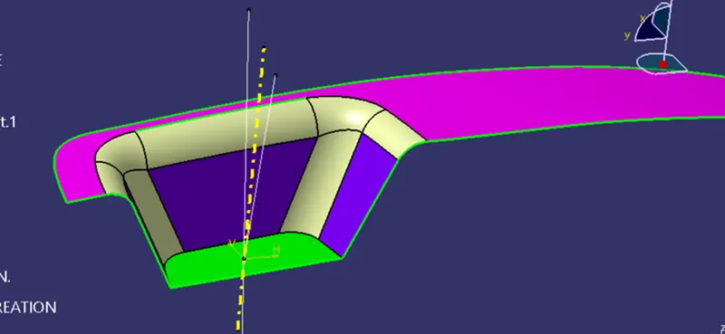
In the switch bezel part the tooling axis is formed by two sketches between XY & YZ planes thereby intersecting the two lines we can generate the tooling axis required. For the tooling axis we generally used bisecting method of the line with a point to get the tooling axis
Bisection method is used to create a proper tooling axis required with the help of the refence axis generated at different planes
Draft analysis:
The draft analysis technique is used to analyze whether our part model created in CAD is manufacturable based on the draft condition applied. Here the part should get easily removed from the Mold. No parts can be ejected from the tool if it is having a straight 90-degree profile from its base surface. A small draft angle is provided to each and every area of the component in order to get easy removal of the component from the tool. Here we are providing a tooling direction in which components should eject in order to get easy removal of components from the tool
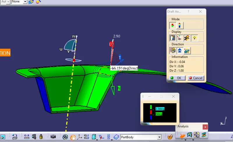
Minimum draft allowed is 0.5mm and maximum draft allowed for engineering component is 3 mm
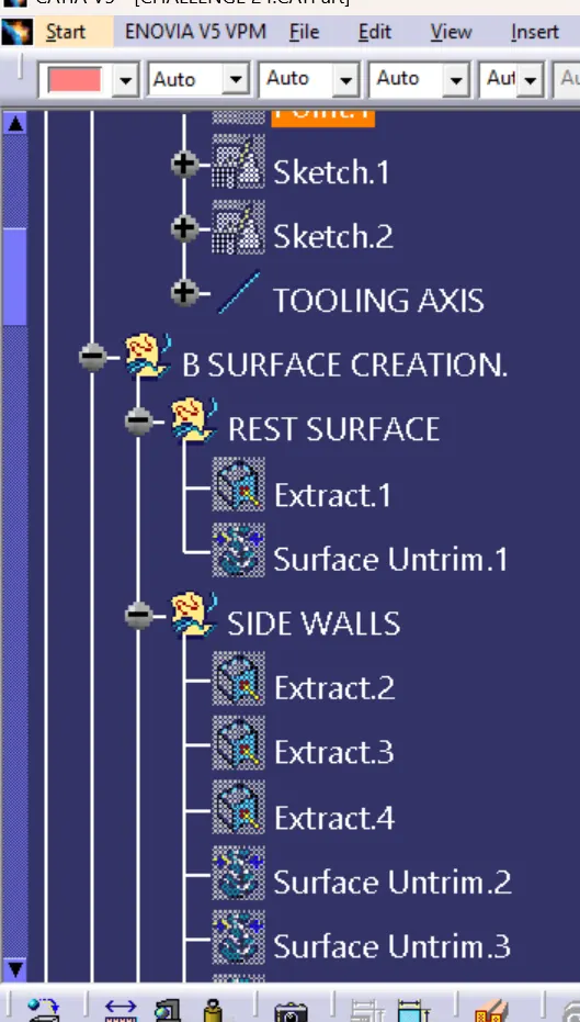
Surface B creation:
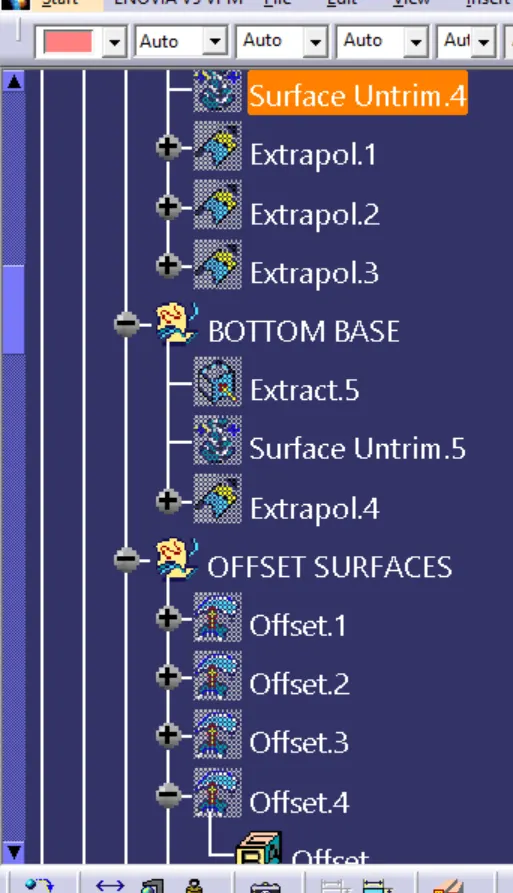
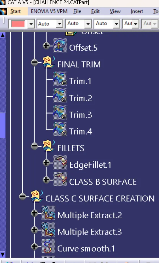
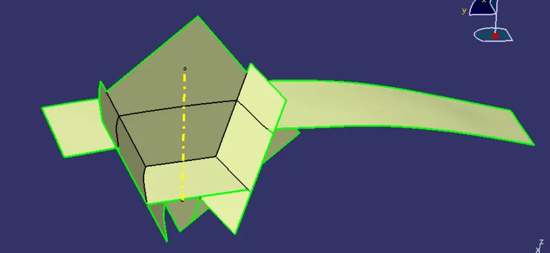
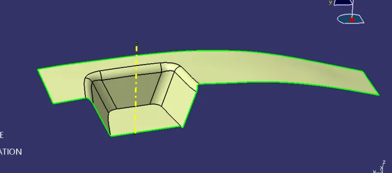
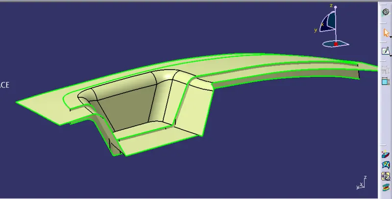
Now generate the B surface using the surfaces of the class A by extracting the surfaces( Resting surface , Walls, bottom face) and untrim them, there by extrapolate the untrim surfaces and final trim the surface with an offset of 2.5 mm with reference to the clss A surface
Surface C creation:
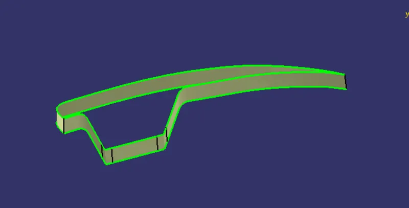
Create a new geometrical set for the class C surface and generate the boundary of the class A using boundary feature or the multi extract feature the sweep the boundary with the tooling axis taken as reference
Surface body:
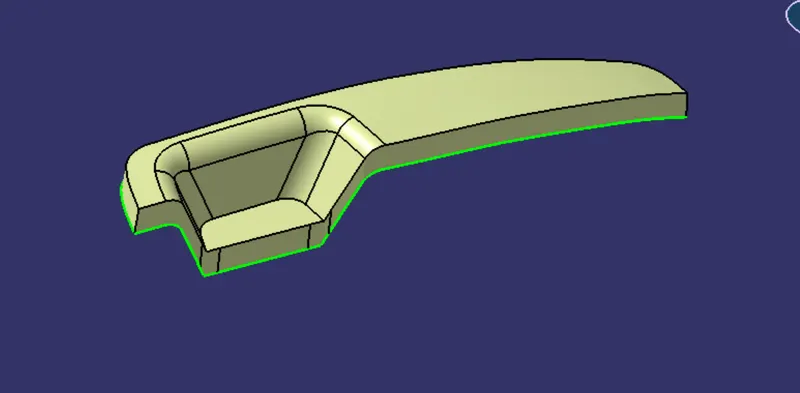
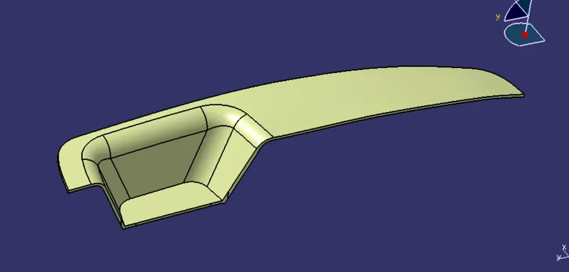
Now join the calss A with Class c surface and trim the joined component with class B surface so the generated component is the surface body
Solid body:
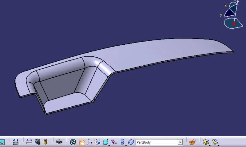
Use the close surface feature in the part workbench to generate a solid body out of the surface body
Parting surface:
The surface which lies on the B surface which seperates Class a and class B surfaces and it helps us to differentiate the core with the cavity block
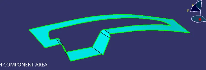
Core design:
Core is defined as the projection of the surface
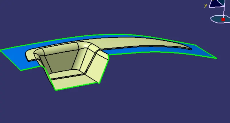
Intially I extract the boundary of the class A surface then extrapolate to an extent of 14mm in curvature continuity with point continuity propogation mode
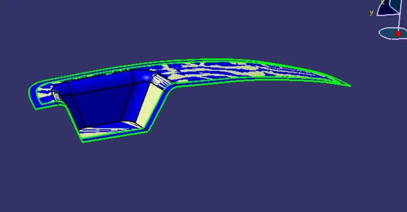
Then use the Joined C and A surface trimmed part and do the trimming with the extraoplate surface and trim the resulted component with class B surface
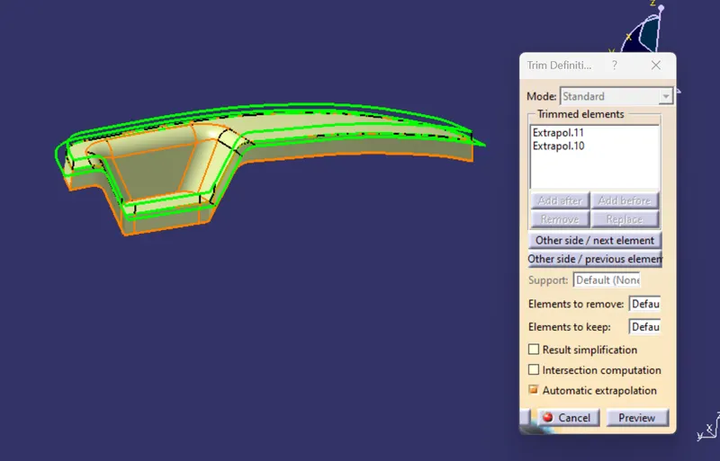
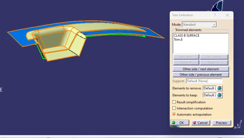
So the resulted trimmed surface is the parting surface with the component area
Core design creation:
First draw a sketch of rectangle so that the entire class A should fit on to it
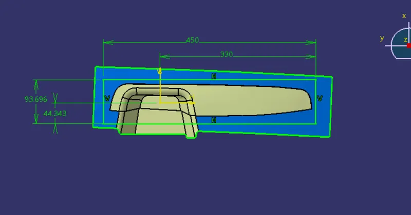
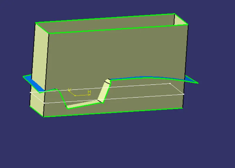
Extrude the rectangle to an extent
 .
.
Trim the extruded surface with the parting surface to forn the core surface
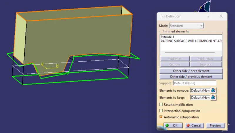
Fill the upper top portion by creating a boundary and use the fill feature option
.Now join the extruded surface with the fill surface
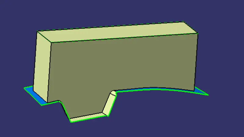
create the solid body of the joined surface by using close surface feature Now the core block is ready
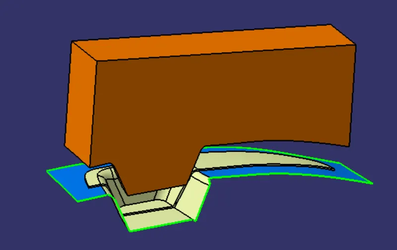
Now intersect the core block, closed surface of switch bezel, and the parting surface to get the clear view of the core and the parting surface
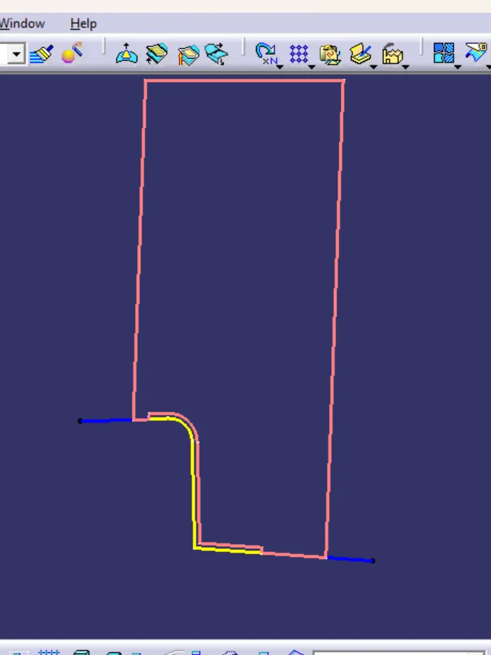
Cavity design creation:
Now use the same rectangle sketch to extend the surface and use the fill to close the open end and trim the surface to obtaion a block

Now overall interection part is
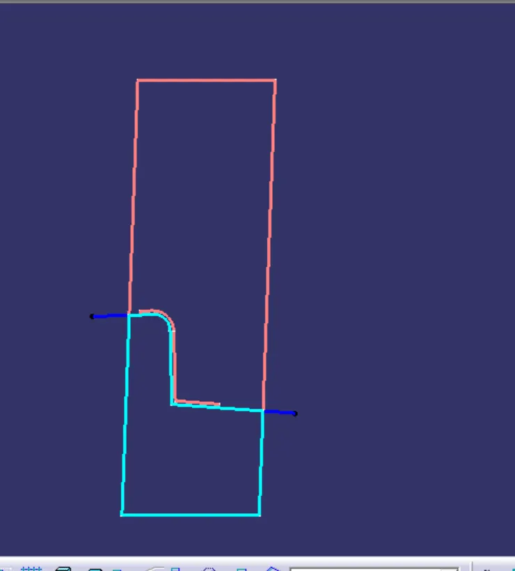
Parting line:
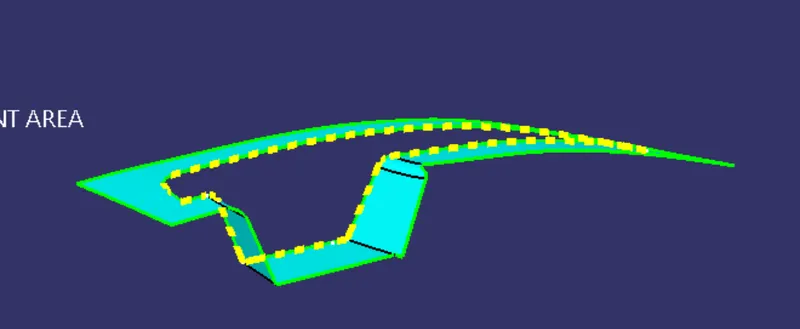
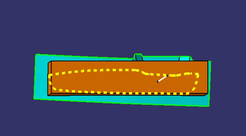
the line at which two closed dies or two halves of a mold meet.It is generated by intersecting the parting surface with the trimmed surface of class A and Class C
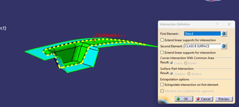
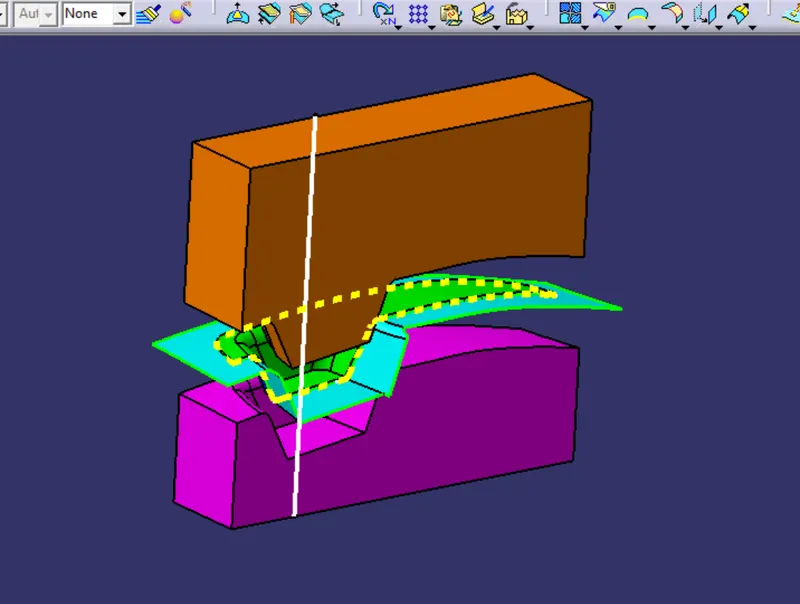
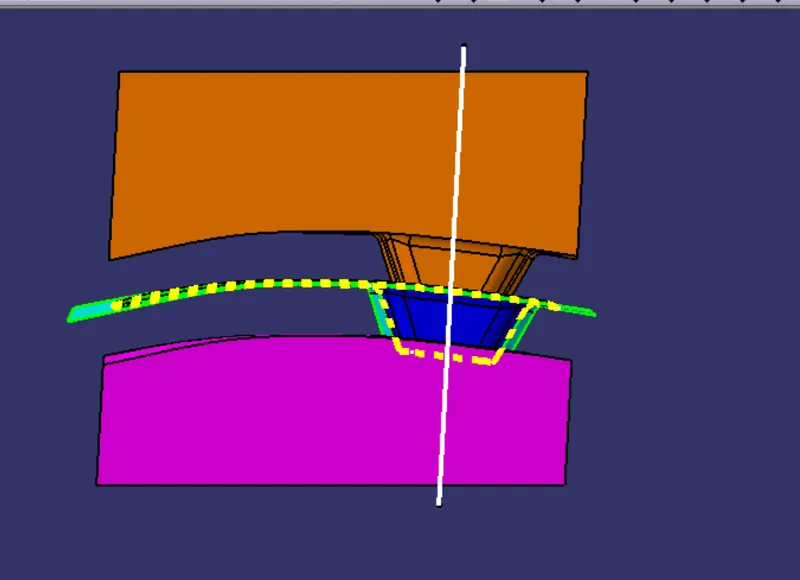
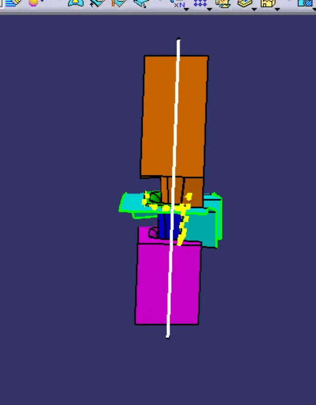
Now project the each and every surface together to get the clear mold design Generally translate the core and the cavity with respect to the tooling axis to get the clear movement of core and the cavity design
Now trim the parting surface with the component area with the parting line to get the required actual parting surface
Conclusion:
so, the core and cavity design is created by using the tooling axis , parting surface and the parting line using catia V 5
views:
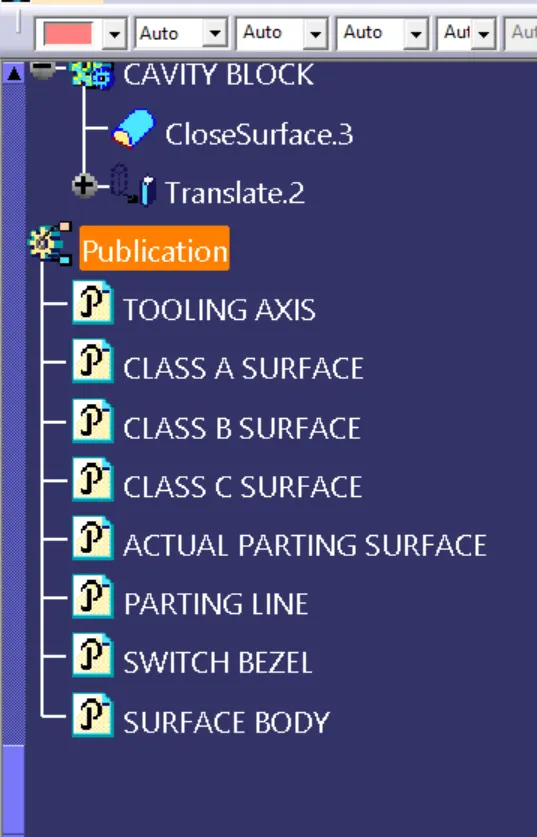
Tree structure