Week 8 - Challenge 6 - Core & Cavity Design
CORE AND CAVITY DESIGN
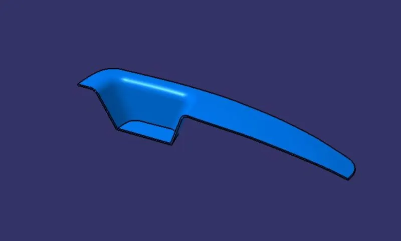
SWITCH BEZEL COMPONENT
DRAFT ANALYSIS OF THE COMPONENT
Draft analysis technique is used whether our part model is created in CAD manufacturable based on the draft condition is applied. Here the part should get easily removed from the panel dies(in case of sheetmetal) or mold (in case of plastic).
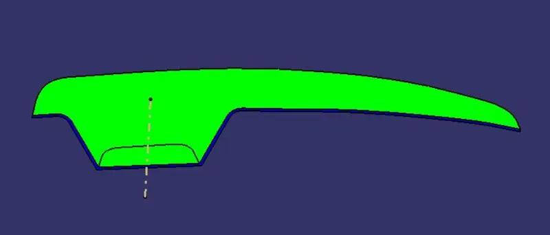
PARTING SURFACE
Designed for the removal of the plastic product and the cold slug, the parting surface is where the core meets the cavity, and locates at the largest section of product.
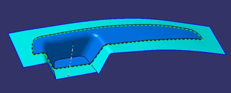
PARTING LINE
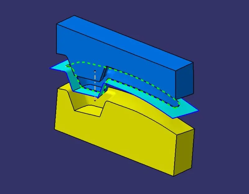
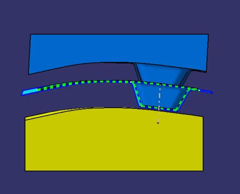
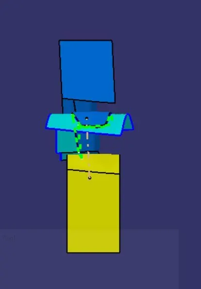
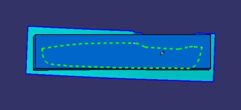
A parting line, in industrial casting of molds, is the border line in which draft angles change direction. One can check the parting line in the mould or product which divides the two half, the core and the cavity of a molded part. It is sometimes a starting point for the mold parting surface.The green dot line are parting line.
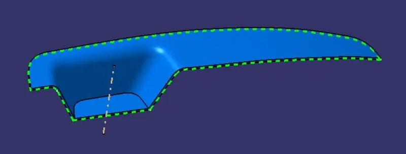
CORE AND CAVITY
Cavity and core are used in the injection molding process, where the concave part of the mold is the cavity and the convex part is the core. The cavity and core are used in pairs, with the cavity also referred to as the female mold and the core as the male mold.
CORE BLOCK
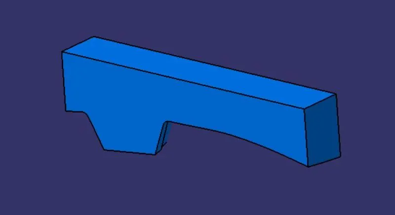
CAVITY BLOCK
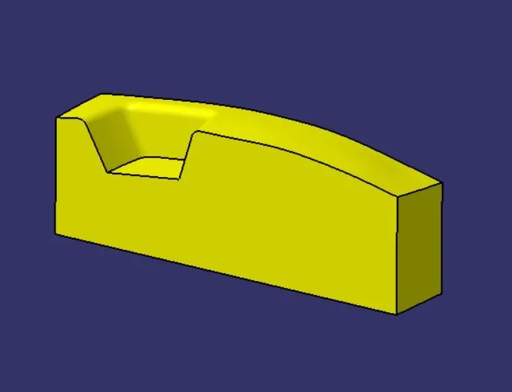
ISOMETRIC VIEW
FRONT VIEW
SIDE VIEW
TOP VIEW
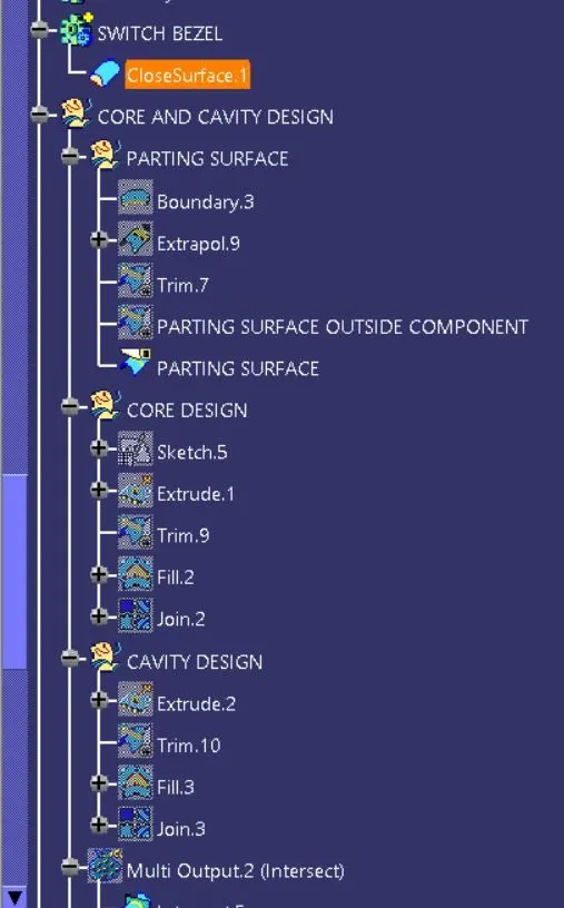
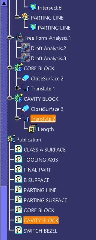
TREE STRUCTURE