Week 8 - Challenge 6 - Core & Cavity Design
CORE AND CAVITY DESIGN
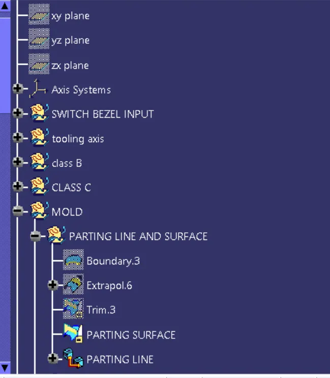
TREE STRUCTURE :
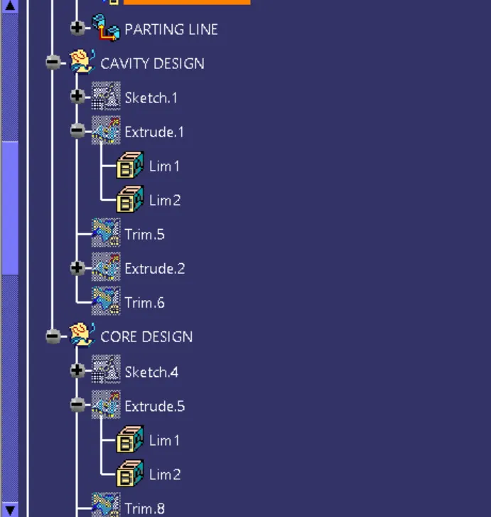
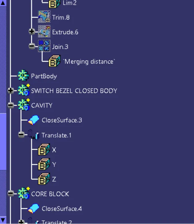
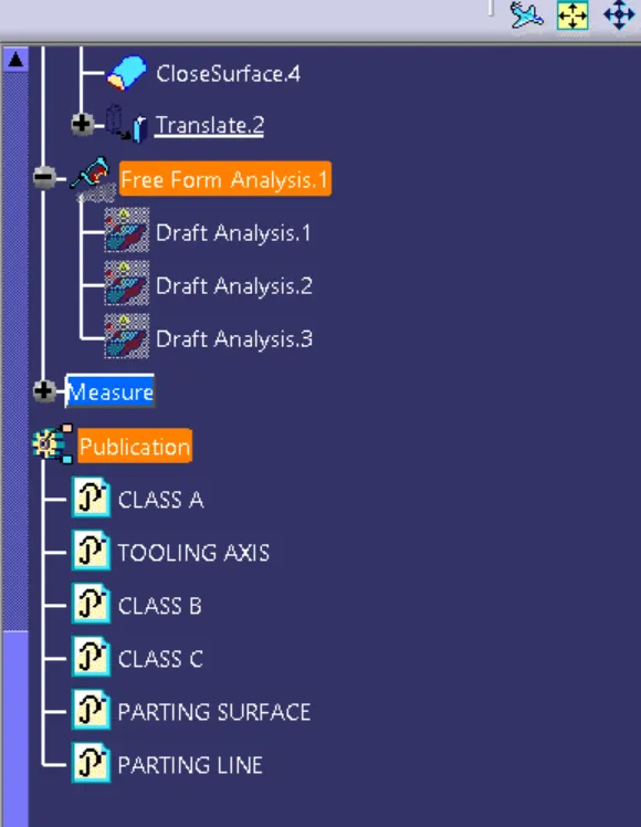
STEPS TO DESIGN CORE AND CAVITY IN SWITCH BEZEL
1. OPEN THE FILE SWITCH BEZEL
2. CREATE THE PARTING SURFACE:
PARTING SURFACE:
Generally , injection mold has two major components the moveable halve and the fixed halve, during injection molding process, these two halves are pressed tightly and form a sealed hollow to avoid the melt flow leakage and maintain certain holding pressure, the pressed suraface are called PARTING SURAFACE , usually parting surfaceare the biggest projection outline of the part.
PARTING SURAFACE DESIGN PRINCIPLES:
Parting surface design directly affects the product quality , ease of construction and operation of the injection mold , the mold design is one of the key factor to success.
steps To create parting surafce:
As parting surafce should lie on the b side suraface, because at the time of ejection of component , there will be one major defects arises, which is called FLASH ( It occurs when some molten plastic escapes from the mold cavity . typical routes for escapes are through the parting line or ejection pin locators. This extrusion cools and remain attached to the finished product ), so to avoid due to aesthic looks on the given class A , WE generally prefered parting surafce on class B side.
1. Take the class A - EXTRAPOLATE to some values,
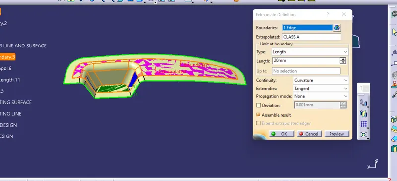
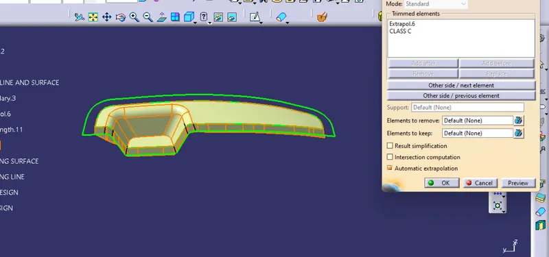
2. take the class c and trim it to get desired output
3. take class b and trim it to get the parting surafce at B side
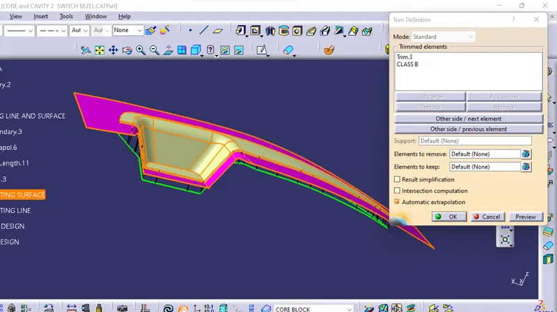
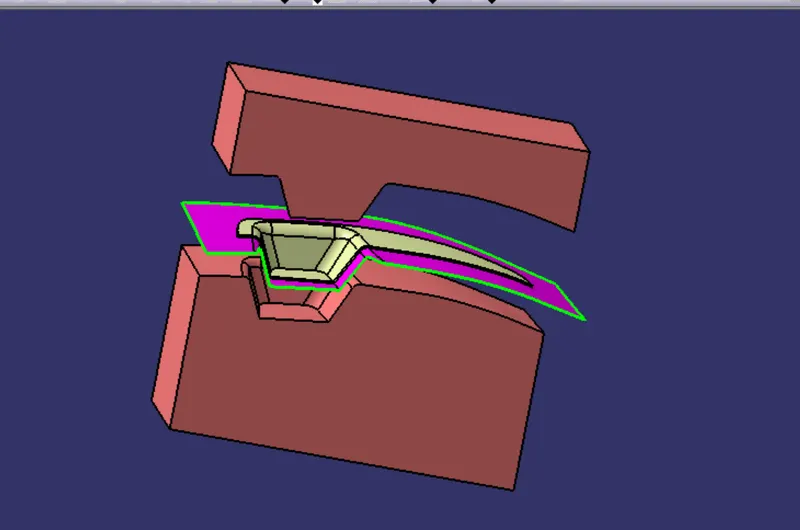
PINK COLOUR one are parting suraface.
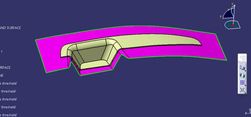
Parting line : It is generally where core and cavity hlaves meet , or in other words , junction between intersection of CLASS (A +C ) JOINS AND PARTING SURAFACE.
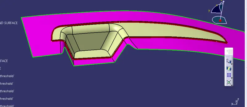
DESIGN OF CAVITY : AS generaally cavity should be at CLASS A side, because cavity is the fixed block , so to prevent from any damage the product , we preferred cavity should be at CLASS A side.
STEPS
1. TAKE THE PARING SURFACE AND DRAW RECTANGLE
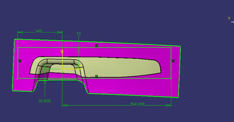
2. EXTRUDE THE RECTANGLE WITH RESPECT TO TOOLING AXIS AND TRIM IT TO GET THE DESIRESD OUTPUT
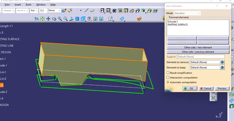
3. JOIN THE CAVITY AND CREATE A SOLID BODY USING CLOSE SURAFACE TO GET CAVITY BLOCK
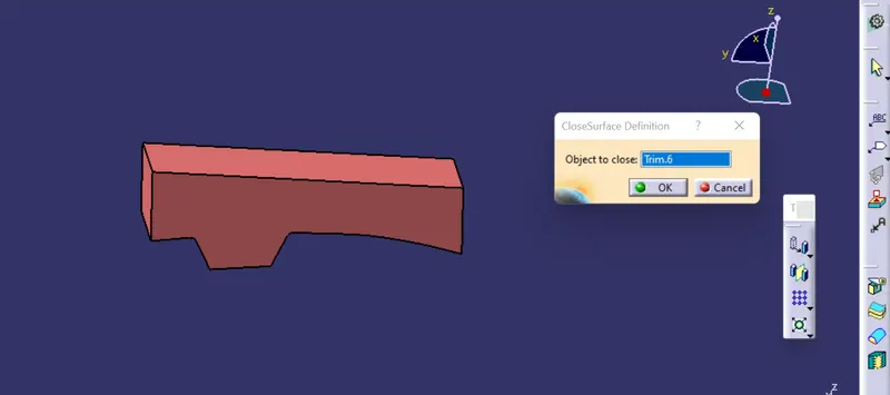
CORE DESIGN : THIS is done on class B SIDE , as core block generaly moves, so while ejecting the core block with ejector pins, there will be chances of some scratch haappened , which will not look aesthetic to view, so AT B side, is not visible to customer, and therefore is the reason to place core at b side.
steps to create core design.
1. take CLASS B
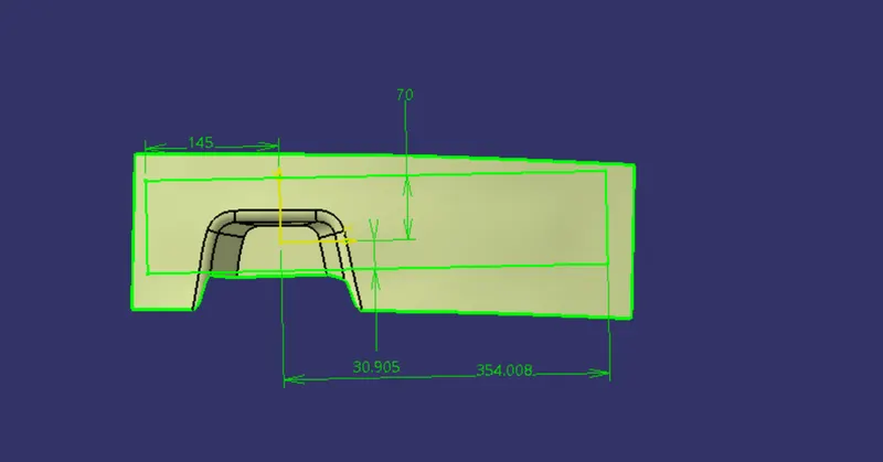
2. DRAW THE SAME RECTANGLE AND EXTRAUDE ALON THE TOOLING DIRECTION
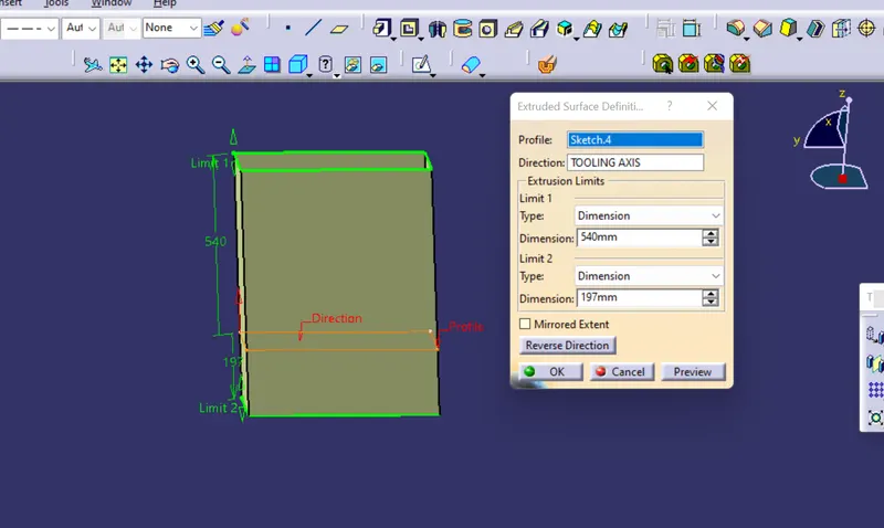
3. JOIN THE SURAFCE AND TRIM IT TO CORE SURFACE
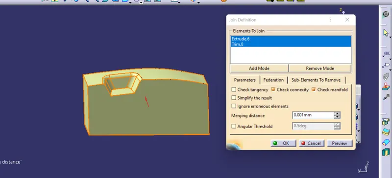
4. CREATE A SOLID BODY USING CLOSE SURAFACE TO GET CORE BLOCK
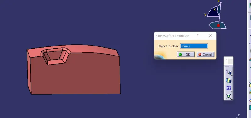
FINALLY CORE AND CAVITY MOLDS READY WITH PARTING LINE AND PARTING SURAFACE.
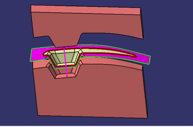
VIEWS
ISOMETRIC VIEW
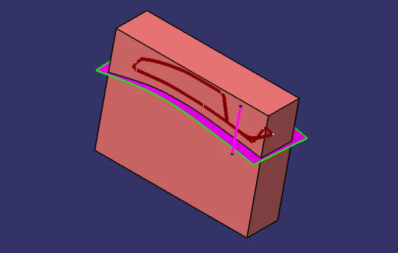
FRONT VIEW
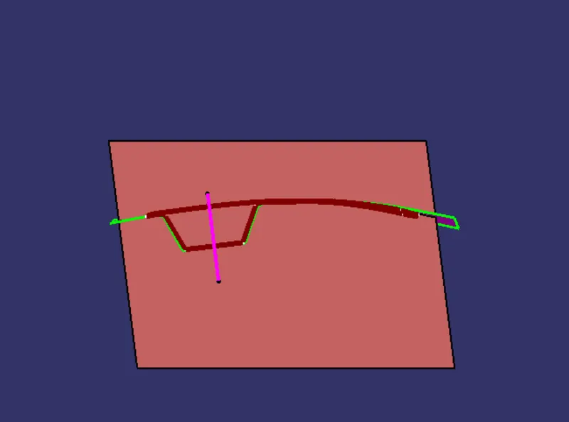
SIDE VIEW
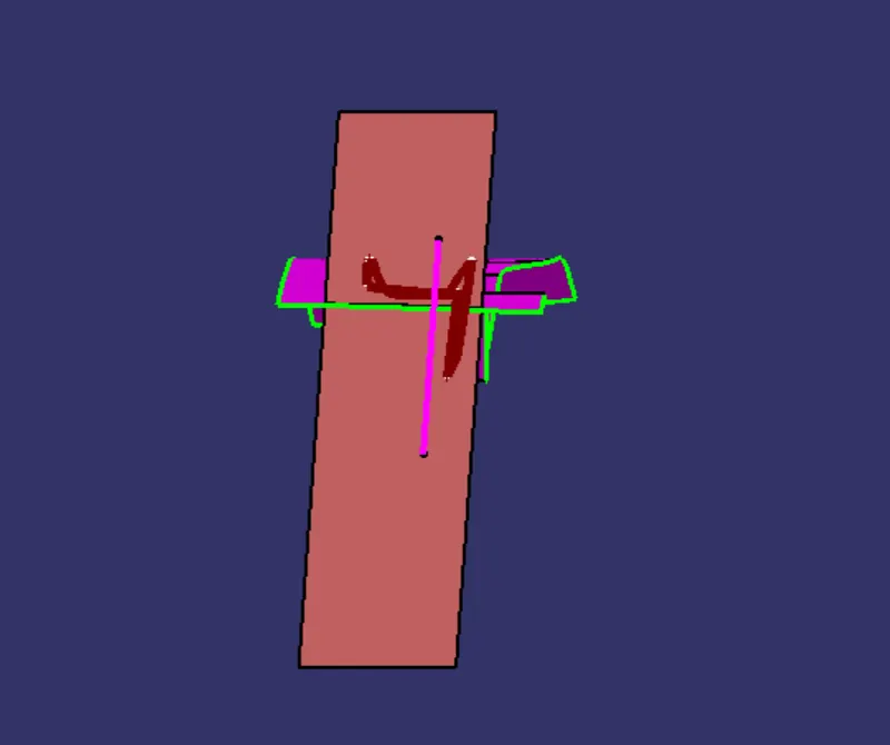
TOP VIEW
DRAFT ANALYSIS : 3 DEGREE DRAFT has been given , and here it is clearing our component.
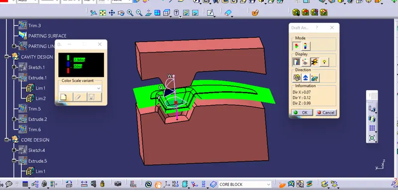
conclusion : here, i have design the core and cavity block .