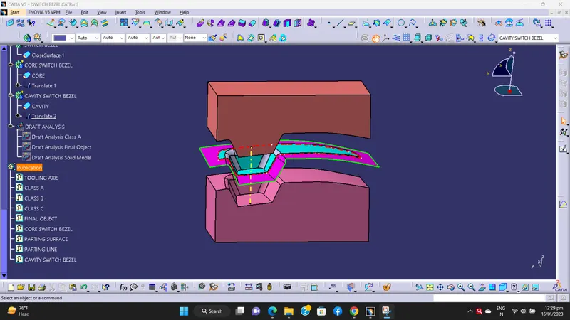
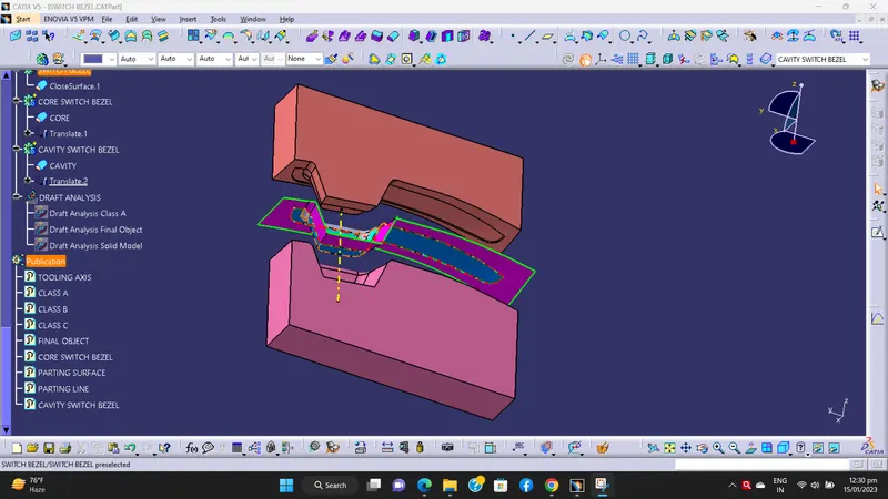
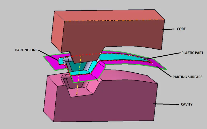
Week 8 - Challenge 6 - Core & Cavity Design
DESIGN CORE AND CAVITY -
DESIGN PROCEDURE -
1) Creating tooling axis.
2) Draft analysis on Class A surface.
3) Creation of parting surface.
4) Creation of core side.
5) Creation of cavity side.
6) Creation of parting line.
ABOUT CORE AND CAVITY -
A core is the one part of the mould and it is respponsible for half of the molded part. Actually core is the projection of the body and cavity is the depression of the body. These core and cavity combines to form a mould. Then the molten plastic material injected into these mould to get a plastic part.
1) Creating tooling axis -
Tooling axis is a line of direction where core & cavity will open.
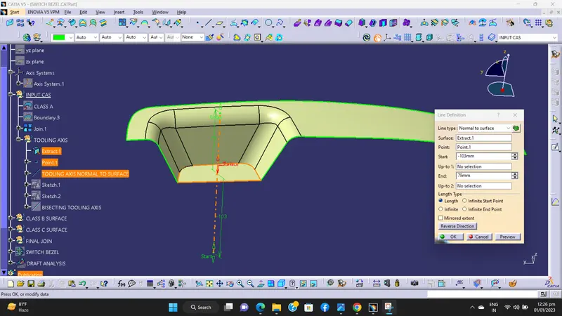
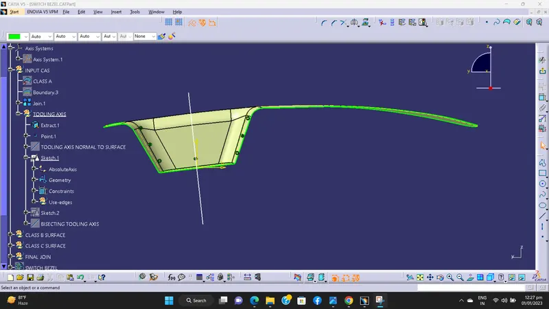
In bisecting method, the base of Class A surface was extracted and a point at the centre is created and an axis system was inserted to the point.
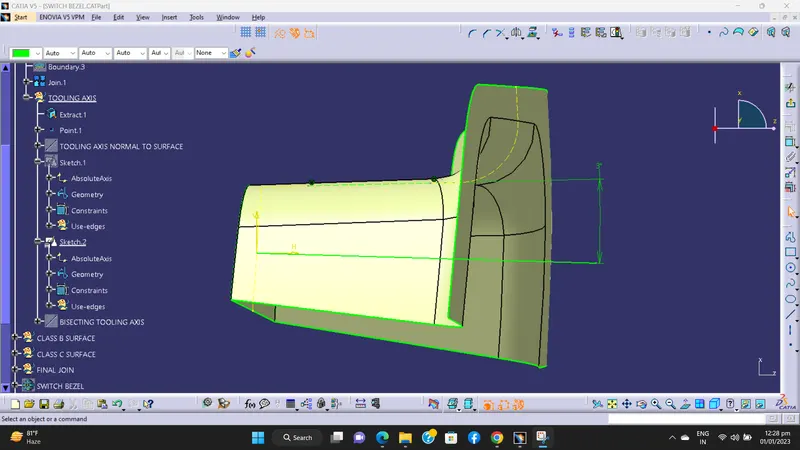
Then we create some sketch by using positioned sketch. In that using project intersection along yz plane is created and the two inclined lines were drawn.
Then bisecting line is created by using this two inclined line.
Now the same procedure is done in sketch two along the xz plane but there on one side we dont have inclined line. So there we creating one horizontal line along with centre point with dimension 3 degree.
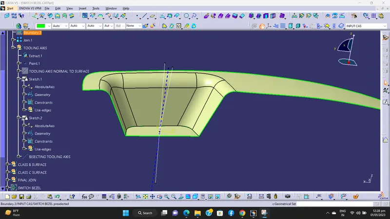
Then bisecting this two line from sketch 1 & sketch 2 we create one more line, which our tooling axis by using bisecting method.
Then by using publication tool tooling axis is published.
2) Draft analysis on Class A surface -
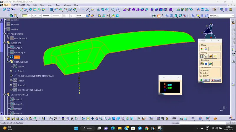
By changing the view mode to custom view parameters – Material mode then the feature draft analysis is enabled.
Then the compass was activated and placed with the tooling axis by dragging the red pointer and then locked it.
Then, by selecting the quick analysis mode, the nominal value will be 3 degrees and checked for the component's draft angle.
The green colour area shows that it satisfies the 3-degree draft angle. If not satisfied then by using the Running point tool the area is measured and then altered to get a successful draft for the created tooling direction.
3) Creation of parting surface -
Generally, injection mold has two major components: the movable halves and fixed halve. During injection molding process these halves are pressed tightly from a sealed hollow to avoid the melt flow leakage and maintain certain holding pressure, the pressed surface called as parting surface, usually parting surface is the biggest projection outline surface of the part.
Parting surface design directly affects the product quality, ease of construction and operation of the injection mold.
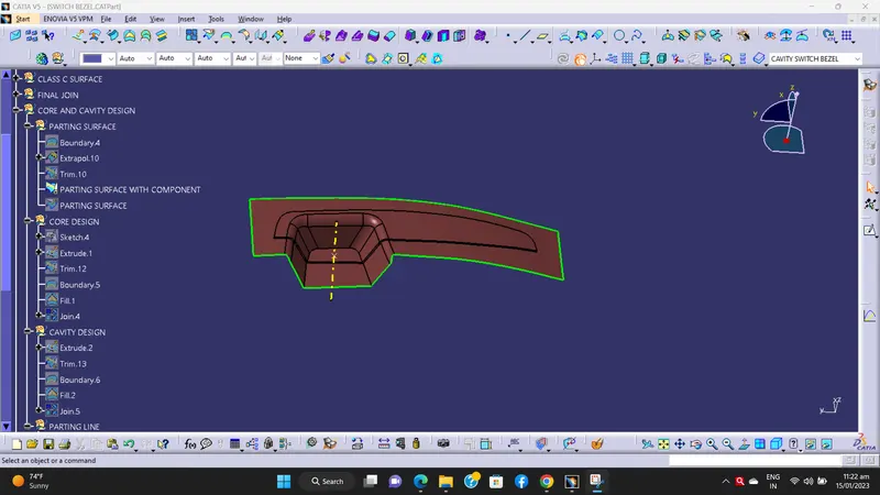
Create boundary on Class-A surface. Then extrapolate this boundary. Trimed this extrapolate surface with Class-C surface.
Then obtain surface is trimed with Class-B surface, we get parting surface with component.
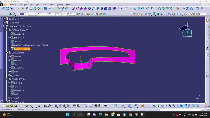
Then by using split command we get only parting surface.
PARTING SURFACE WITH COMPONENT -
PARTING SURFACE -
4) Creation of core side -
Create block sketch on XY plane. Then extrude with require height.
Then trim with parting surface with component. After that fill the top side of core and then join.
We get our core side.
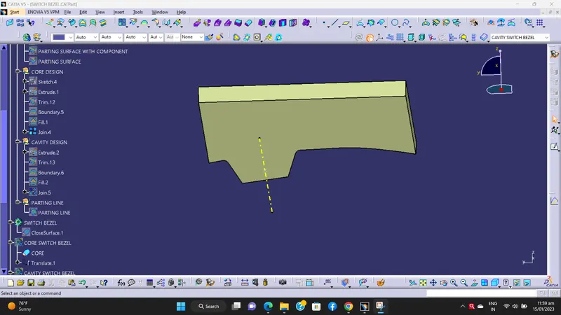
After in part design workbench using close surface command core get in solid body.
5) Creation of cavity side -
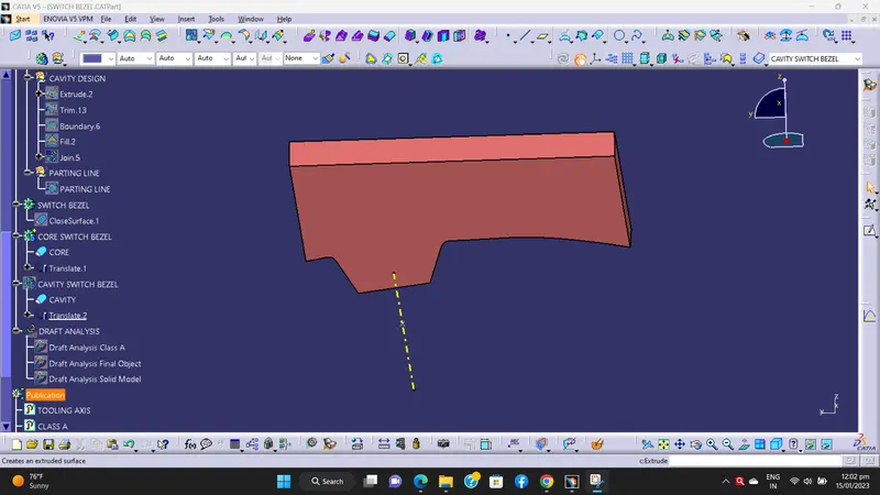
Extrude created block sketch with required height. Trim with Class-B surface.
After that fill the bottom side of core and then join.
We get our cavity side.
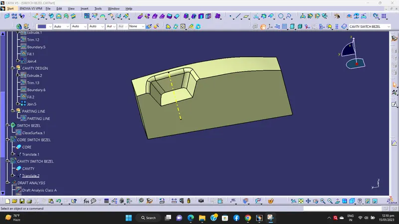
After in part design workbench using close surface command cavity get in solid body.
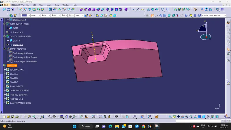
6) Creation of parting line -
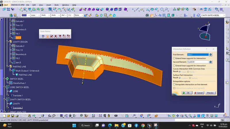
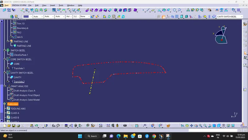
Create intersection between the join of Class-A surface and Class-C surface and Class-B surface.
This intersection line is nothing but parting line.
ALL COMPONENTS OF CORE AND CAVITY -