Week 8 - Challenge 6 - Core & Cavity Design
Objective:
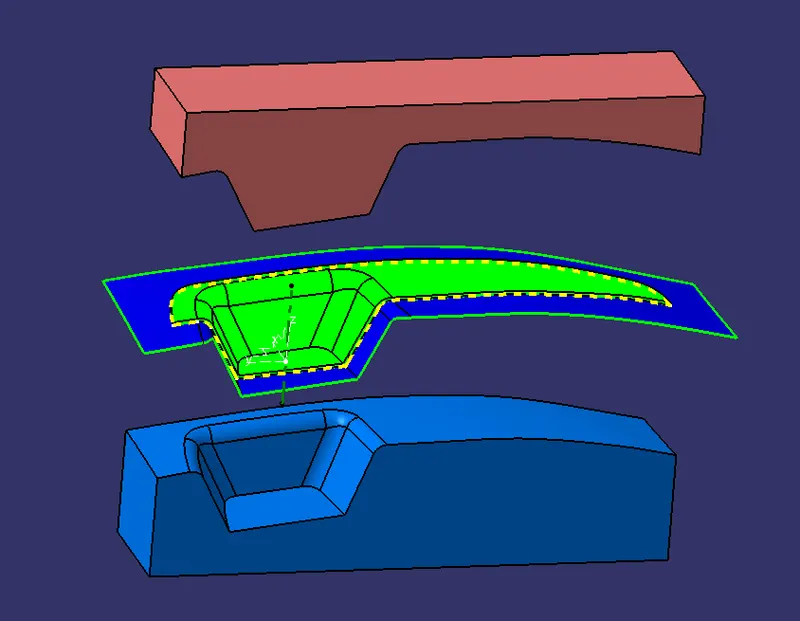
To Create the Core and cavity blocks for the switch bezel designed in the earlier challenge.
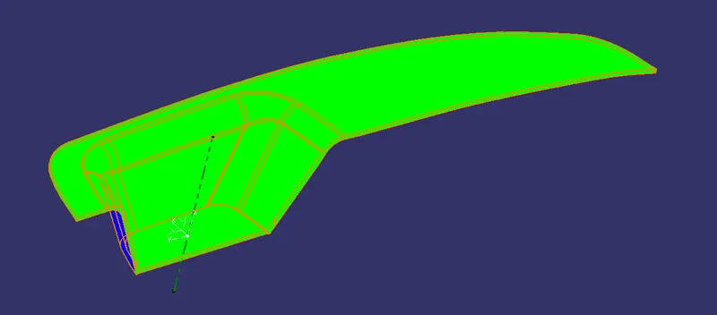
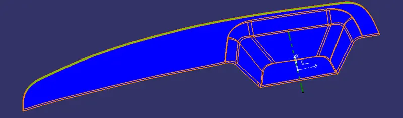
DRAFT ANALYSIS OF COMPONENT:
CORE DESIGN:
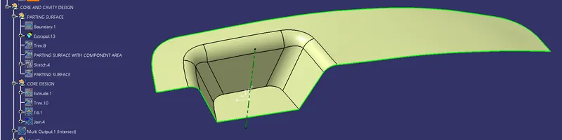
As a First step The boundary of the Class A is exptrapolated. After extrapolation the surface is trimmed with class C and Trim 8 is creaded. Using this Trim 8 and class B surface another trim is done and this the Parting surface. This parting surface cosists of the exploated region, Class A and Class C.
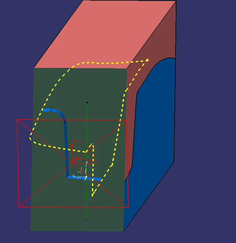
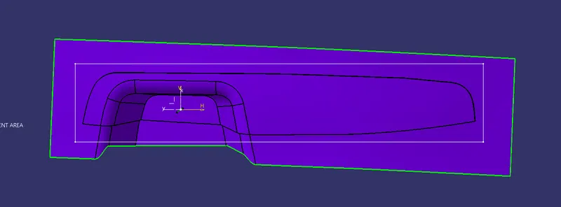
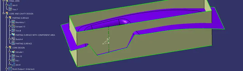
By selecting the XY plane and drawing a rectangle so that it can cover the part with the parting surface upto some distance. By using this rectangle and tooling axis extrude operation is done.
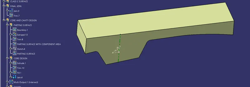
By using this extrude and parting surface a trim operation is done. Then the top open region is filled by creating a boundary and joined together.
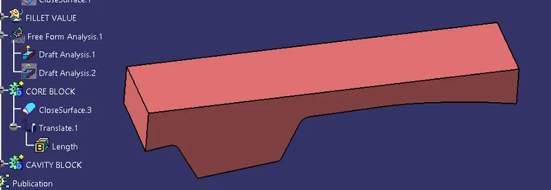
Using the Joined surface and checking for any open area using boundary option and it is formed as a part body using closed surface command.
Thus core is created.
EXTRAPOLATED SURFACE
CLASS A WITH CLASS B
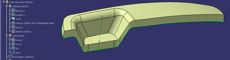
PREVIOUS TRIM WITH CLASS B
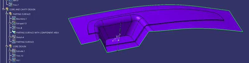
RECTANGULAR SKETCH
EXTRUDE
TRIM OF EXTRUDE AND PARTING SURFACE
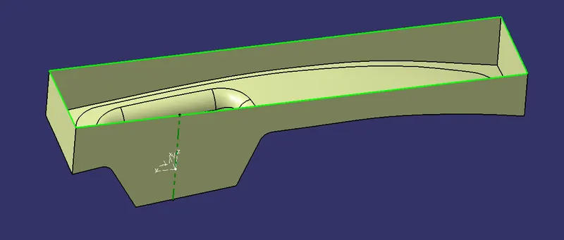
FILLED OPEN SURFACE
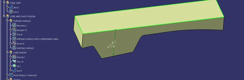
JOIN OF FILL AND TRIM
CORE BLOCK:
CAVITY DESIGN:
To create cavity block, The rectangular extrude and parting surface are trimmed in such a way to form the cavity side. Then the open region is closed using fill option and joined together. This joined feature is formed a closed body for cavity Block.
TRIM OF CAVITY SIDE
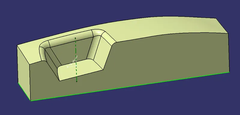
FILL OF OPEN REGION
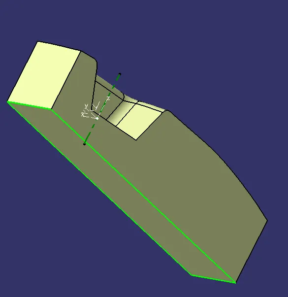
JOIN OF BOTH TRIM AND FILL
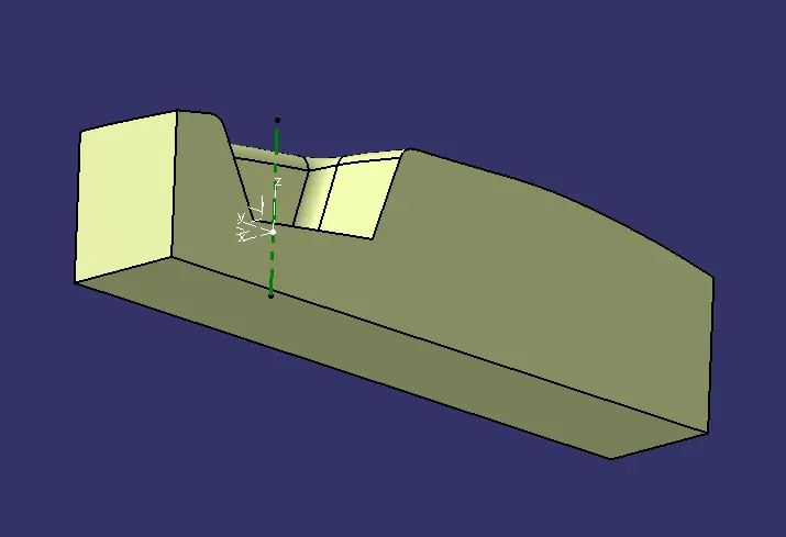
CAVITY BLOCK FORMED USING CLOSE SURFACE COMMAND:
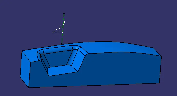
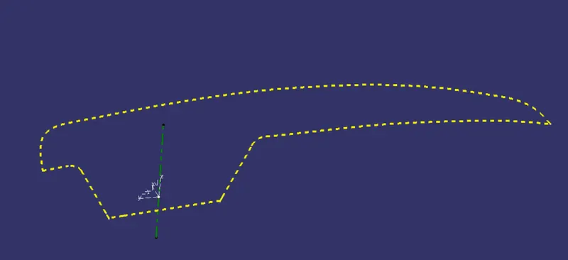
PARTING LINE:
To create a parting line I take an intersection of class b surface and class c surface (class c surface- join of class A and sweep).
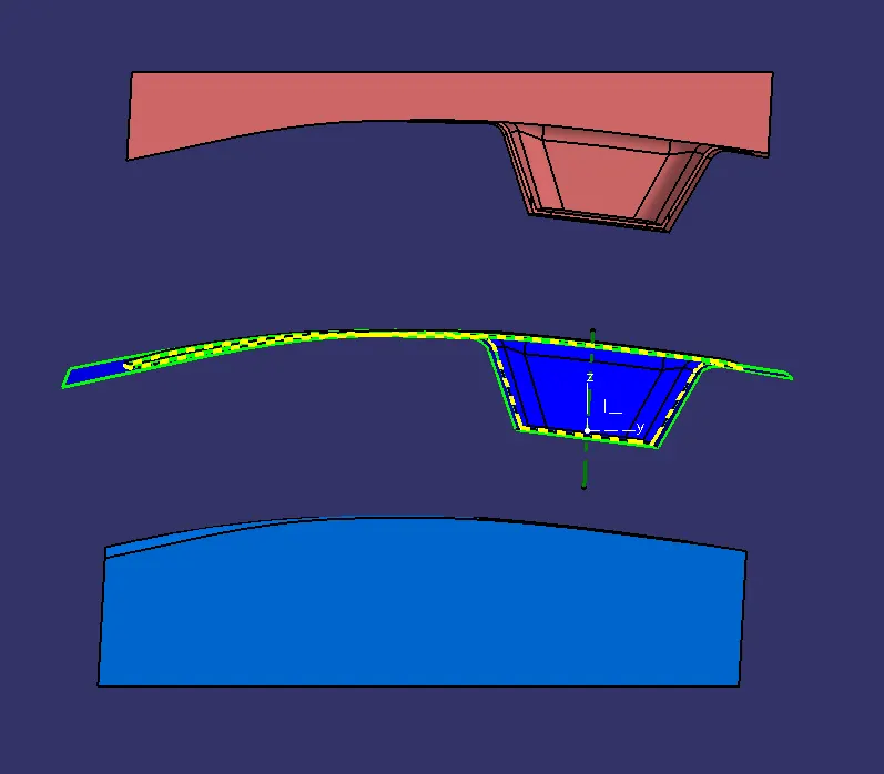
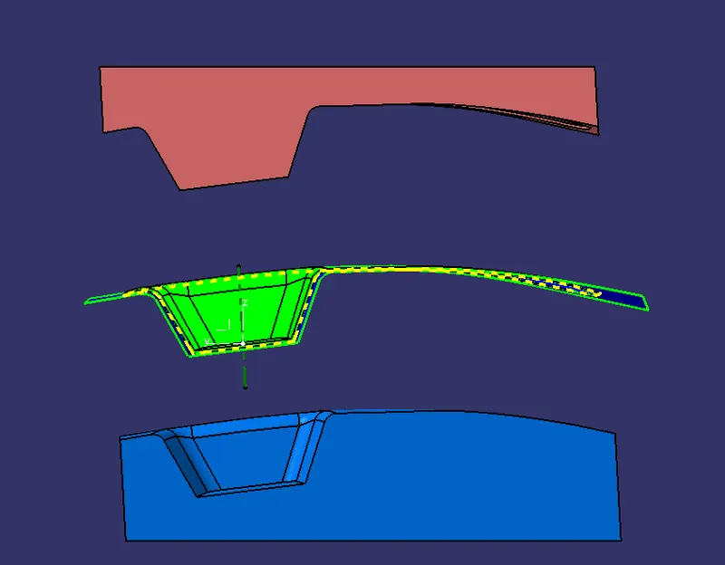
EXPLODED VIEW OF CORE, CAVITY AND COMPONENT(SWITCH BEZEL):
FRONT:
BACK:
LEFT:
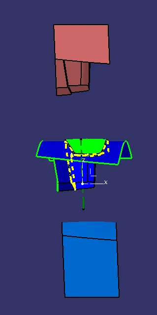
RIGHT:
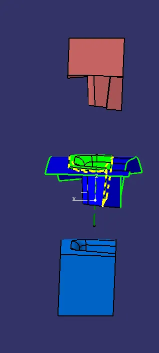
TOP:
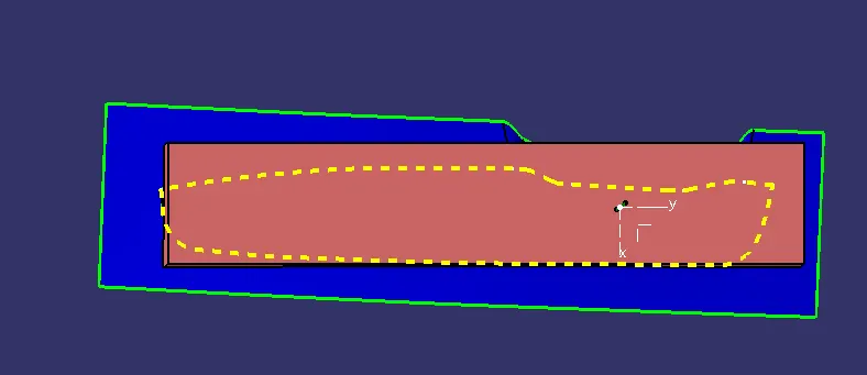
BOTTOM:
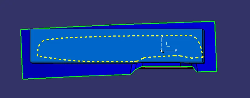
COMPONENT REGION BETWEEN CORE AND CAVITY (SECTIONAL VIEW):