Week 8 - Challenge 6 - Core & Cavity Design
REPORT
OBJECTIVE
To Create the Core and cavity blocks for the switch bezel component.
TOOLING AXIS CREATION
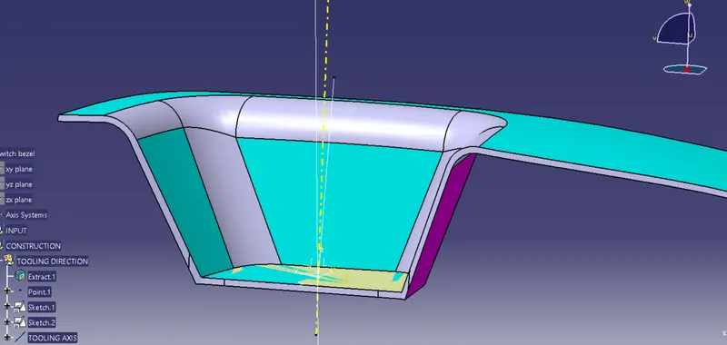
The starting will be from the creation of tooling axis. we need to select the tooling axis so as it is the optimum orientation for the component production in real life. Generally, first we look if its okay for the tooling axis to be in the XYZ directions. If thats not possible, then we will look for large, flat surface and take the tooling axis normal to the surface. If that is also not possible, then we will create tooling axis with bisecting method.
Here, the tooling axis created using the bisecting method.
SOLID BODY CREATION
The Switch bezel plastic component is created from the input class A surface. (Week 8 - Challenge 2 - Switch Bezel Design)
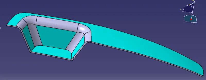
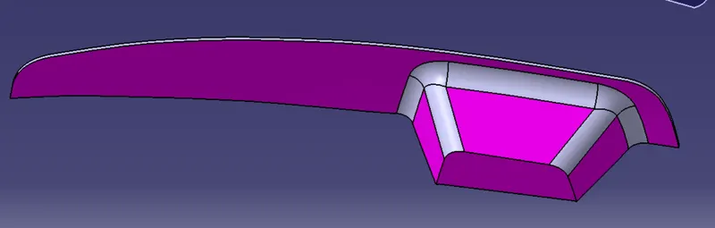
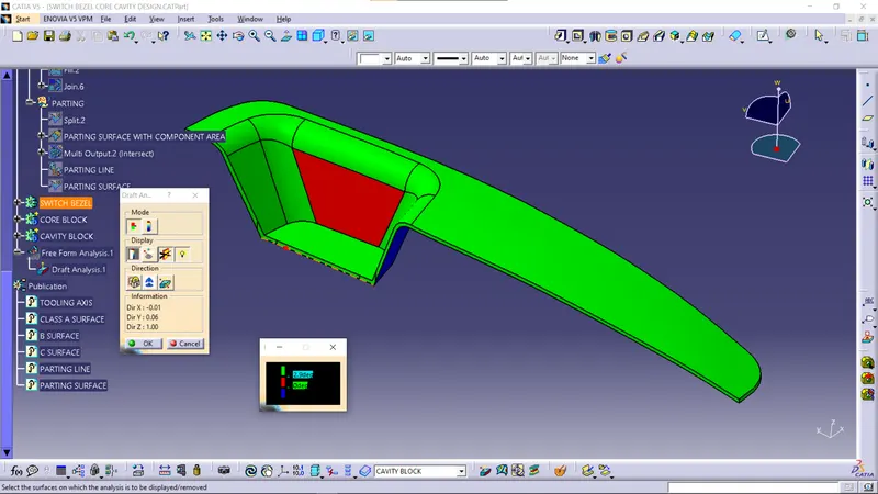
DRAFT ANALYSIS
The Draft Analysis command enables you to detect if the part you drafted will be easily removed. This type of analysis is performed based on color ranges identifying zones on the analyzed element where the deviation from the draft direction at any point, corresponds to specified values.
PARTING SURFACE
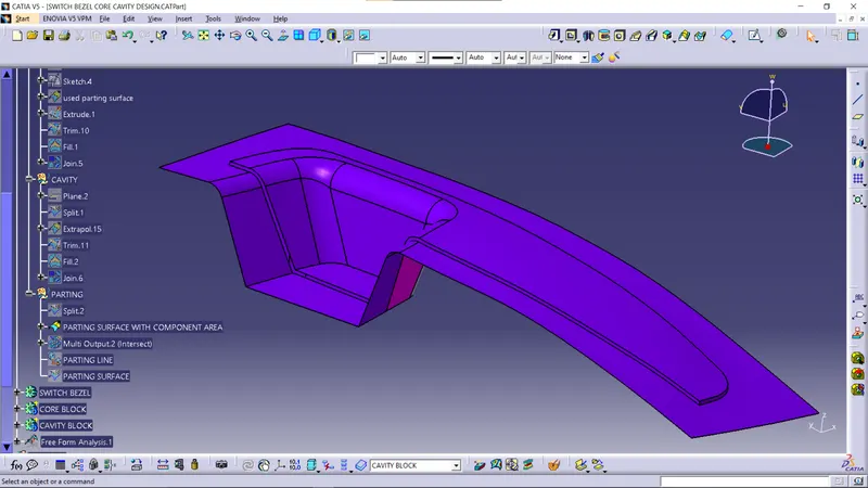
A parting surface is created by trimming class A surface with the C surface, and then with the B surface as shown in the figure.
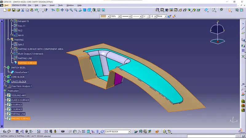
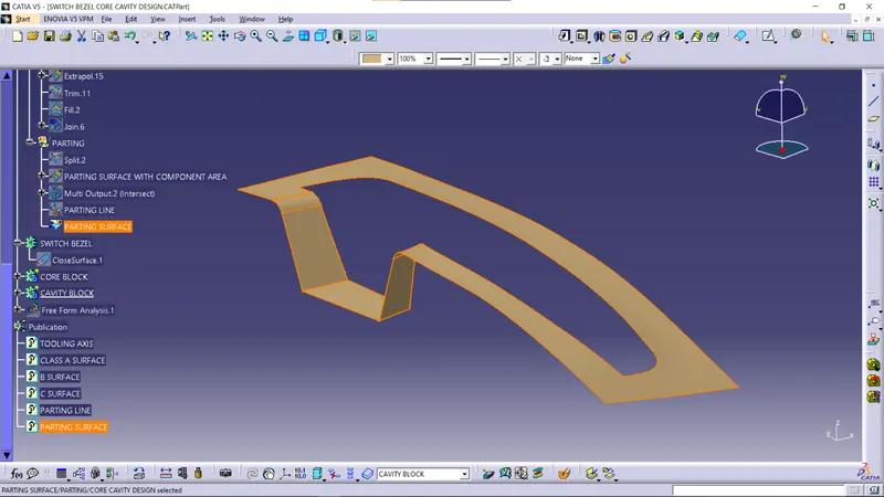
This is the area where both the core and cavity block comes in contact with and closes tightly.
PARTING LINE
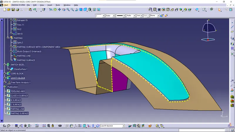
It is the line where the cavity block, core block and the component comes in contact together.
It is the line of separation between where two halves of a mold meet.
If inspected carefully, we can see this line in plastic products like plastic chairs, containers etc.
CORE AND CAVITY DESIGN
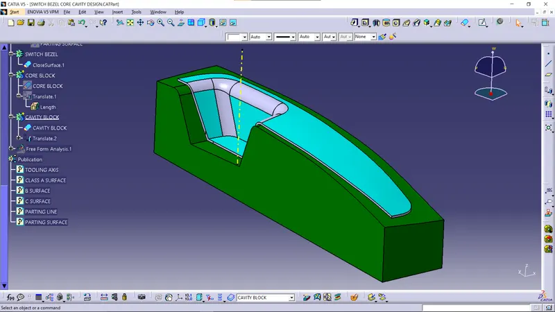
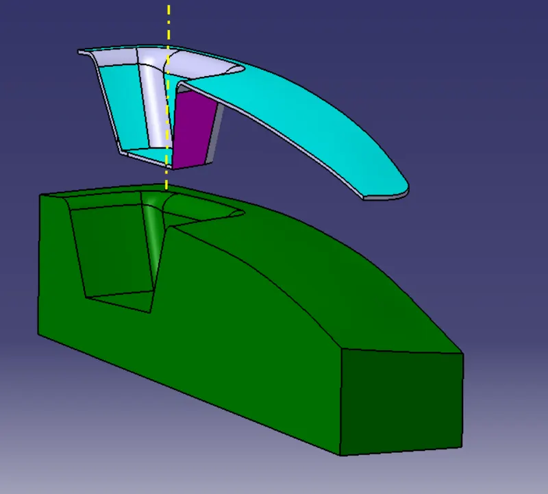
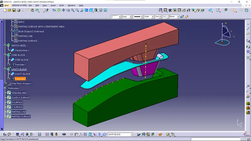
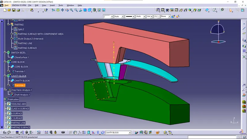
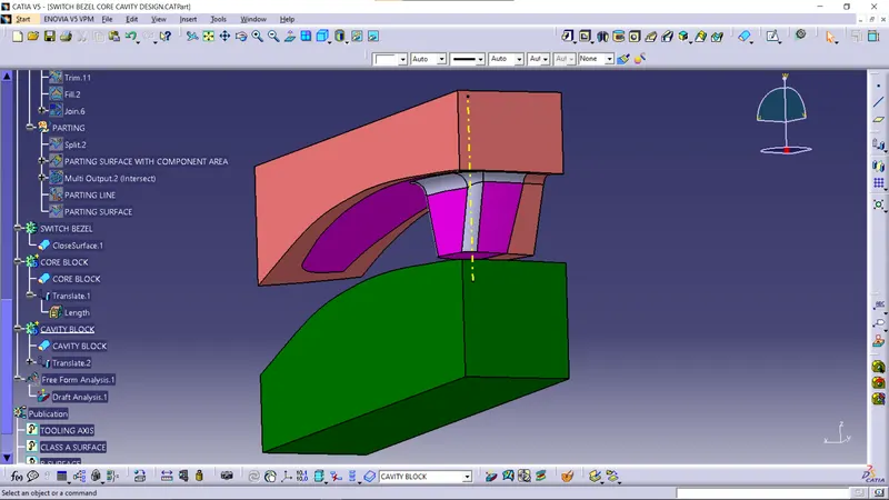
The core is created from trimming the parting surface with a rectangular extrude made with respect to the tooling axis, and then converted the closed surface into solid.
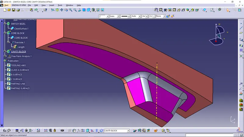
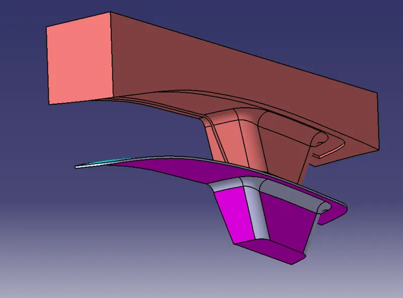
Similarly, cavity is also made by trimming the extrude with the class B surface.
INTERSECTIONS
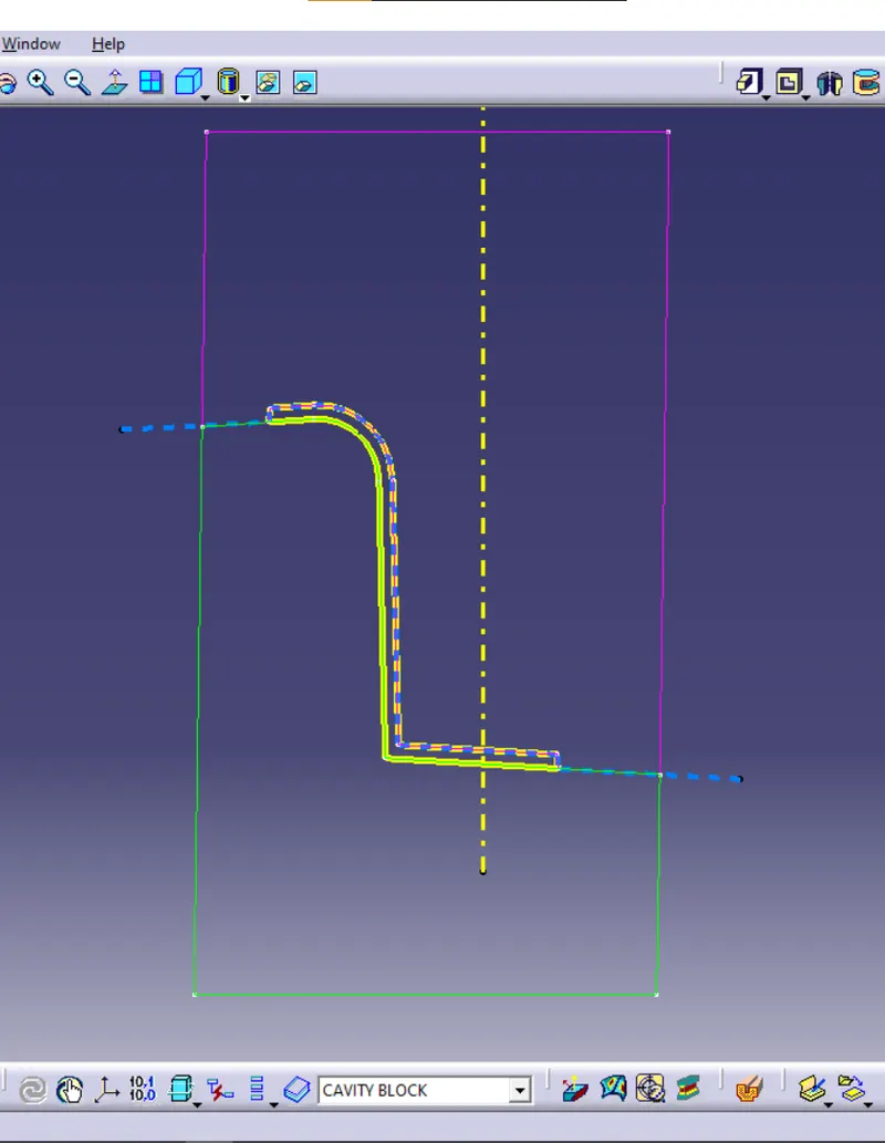
The thin pink and green lines represents the core and cavity blocks, the thick yellow closed profile is the component and the thick blue dotted line is the parting surface(yellow vertical dotted line is the tooling axis).
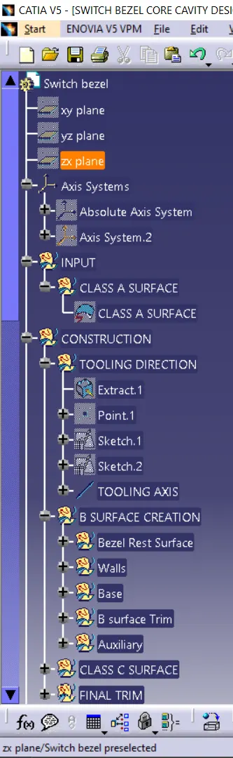
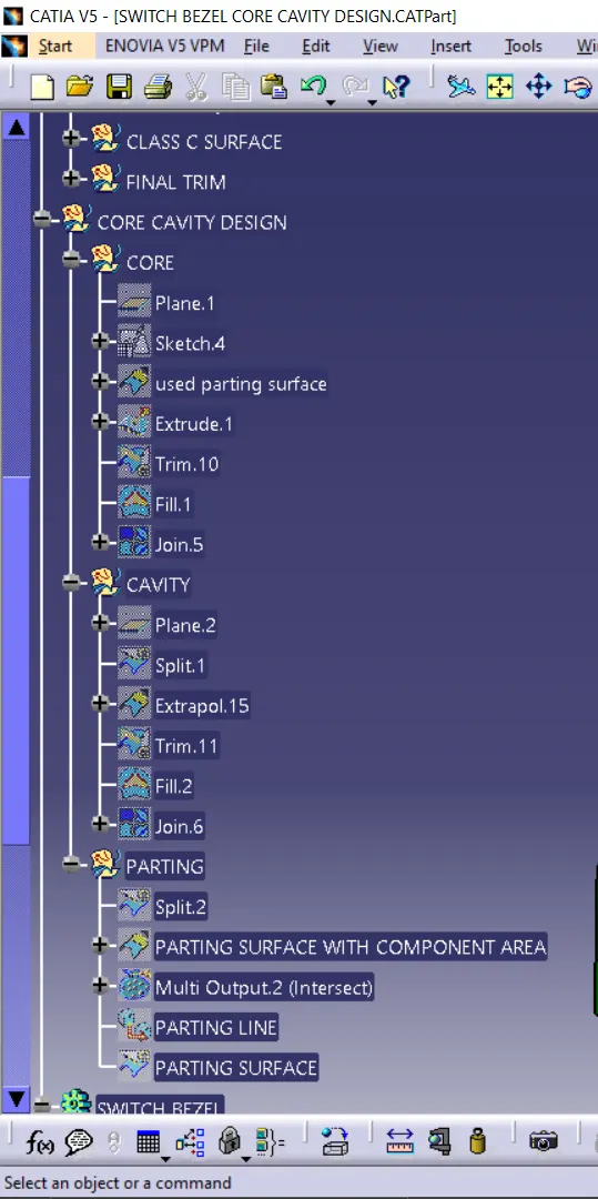
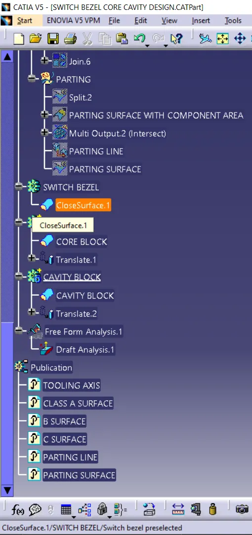
TREE