Week 8 - Challenge 6 - Core & Cavity Design
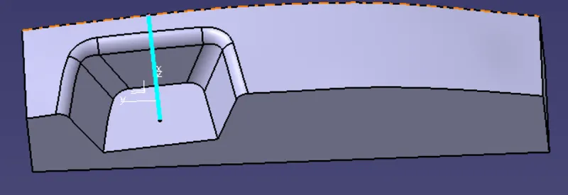
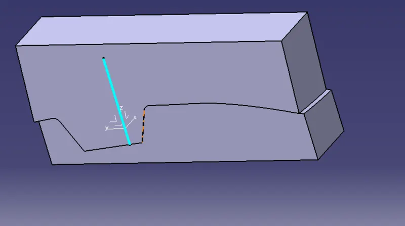
AIM: To create the Core and cavity blocks for the switch bezel designed in the earlier challenge.
Objective :
To design core and cavity for switch bezel with 3 mm thickness
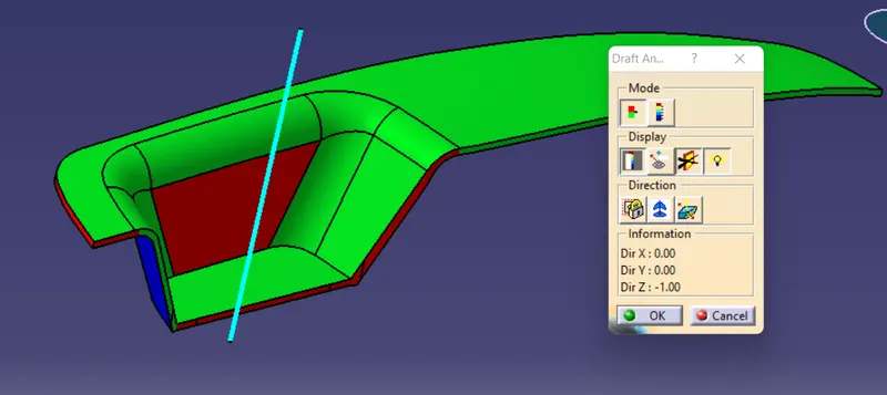
Performing draft analysis to verify the creation of the Tooling axis and C Class surface.
Draft Analysis:
The Draft Analysis command enables you to detect if the part you drafted will be easily removed. This type of analysis is performed based on color ranges identifying zones on the analyzed element where the deviation from the draft direction at any point corresponds to specified values.
In the molding process the molded parts have to eject from the die so there are some issues while removing the molded parts it may get sticky with the die, or while removing chances to get damaged, so we need to set up is the draft angle this draft angle helps the molded parts to eject from the die easily. the standard of OEM for the plastic components draft angle should be in 3 degrees and if it is sheet metal component 7 degree should be the draft angle, This draft is get analyzed and ensuring the part is with proper draft angles.
Core and Cavity:
The core & cavity are the shaped sections in either half of the mould tool which give the plastic product its final shape. The hot molten material is injected into the core & cavity and then sets hard into shape. The design of the core & cavity is essential in the correct formation of the product.
Design Methodology with images:
Procedure for Parting Surface:
- Extract the Class A surface boundary lines with boundary option.
- Extrapolate the Class A surface by 15mm.
- Trim the extrapolated surface with Class C & B surfaces respectively.
Procedure to design Core:
- Open the new sketch in XY plane.
- Create a rectangle and constraints it.
- Extrude the sketch on both sides.
- Trim the parting surface with the above surface of the rectangle.
- Fill the open surface with the Fill option.
- Join the filled surface with the trimmed surface.
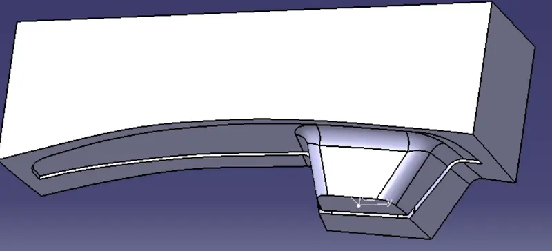
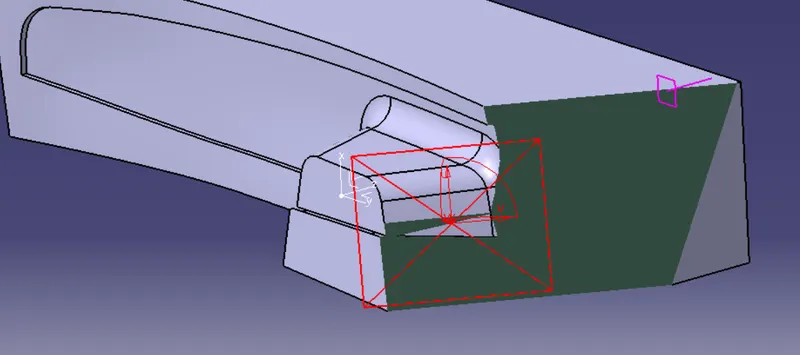
Procedure to design Cavity:
- Trim the extrude surface with b surface.
- Fill the open surface with the Fill option.
- Join the filled surface with the trimmed surface.
- Now open the Part body.
- Create two bodies separately and create closed surfaces.
- Intersect with the perpendicular plane and unhide the tooling axis.
- Translate the bodies in required directions.