Week 8 - Challenge 6 - Core & Cavity Design
CORE AND CAVITY DESIGN
AIM:
- To Create the Core and cavity blocks for the switch bezel component.
DESCRIPTION:
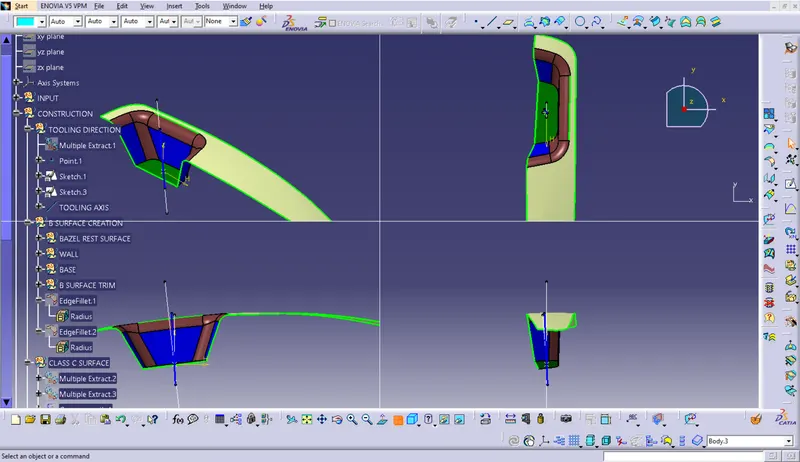
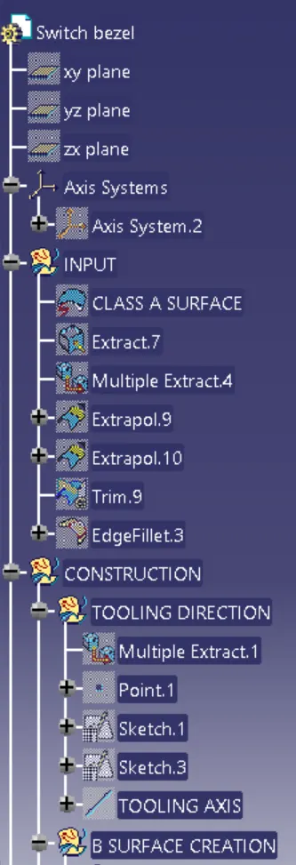
Tooling axis
- Class-A surface is first analyzed to create the tooling axis or tooling direction that molds pull apart in injection molding.
- Tooling direction is important for plastic product design as it decides direction for mold seperation.
Publication:
- Publications allow you to modify a model without invalidating the features defined in the analysis document.
- If you modify the entity to which a publication refers in a CATIA V5 part or assembly, all of the features in the analysis document using that publication are updated to refer to the new entity.
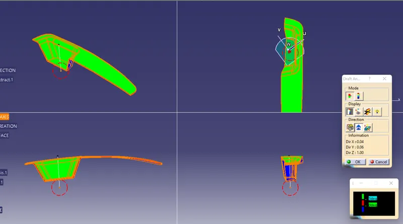
Draft Analysis:
- Draft allows for the component to release from the mould, most parts or applications require a minimum of 0.5 to 1 degree draft angle and 3 dgree draft angle is widely used as per the norm.
- Change the material mode to customize mode before moving to the draft analysis.
- Insert –analysis-feature draft analysis
- Defining the draft direction Select draft analysis from the tool bar and click on the compass symbol and pull the compass from the right side top corner of the workbench and place it on the component where want to do the draft analysis. ‘W’ of the compass and tooling axis should be aligned on the same line.
- Once the compass is aligned with the tooling axis click on the lock symbol and drag on the surface we will get a wrong mark then select that point a table will appear it shows the draft value on the table we can adjust the draft value and analysis it for all the edges and surfaces.
- By clicking the on the surface and using the flipping tool we can assign the Flipping direction, the color of the surface change as per the flipping direction .
- Analysis under running point and move the mouse on the surface and it will show the details of the surface deg direct at each and every point of the surface.
Parting Surface:
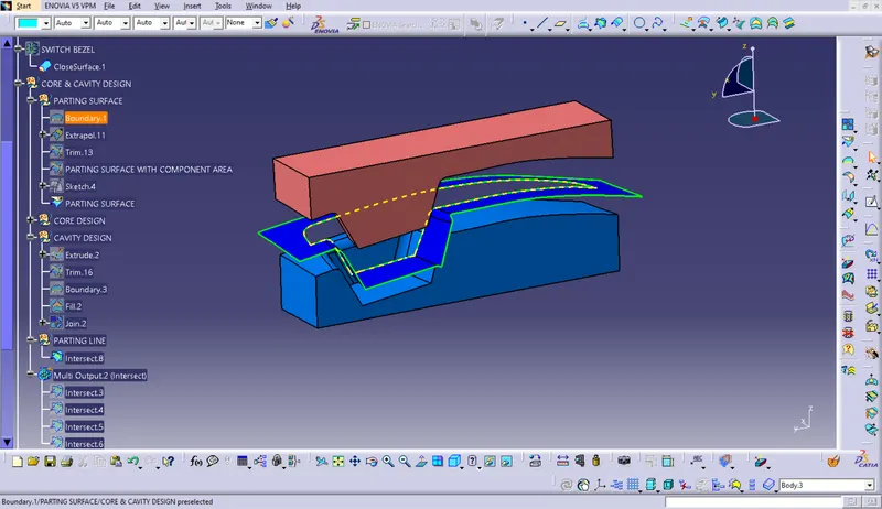
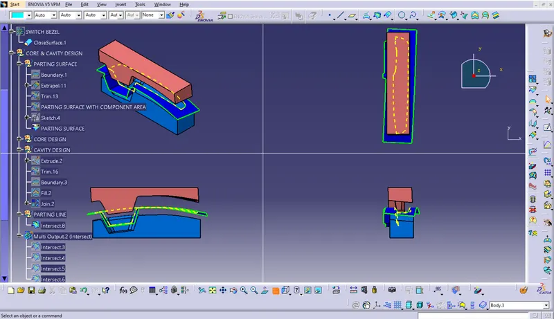
- Designed for the removal of the plastic product and the cold slug, the parting surface is where the core meets the cavity, and usually locates at the largest section of a product.
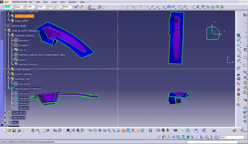
- Blue colour surface shown in pic is the parting surface
Parting line:
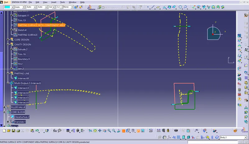
- The parting line is where the two halves of the mold meet around the parameter of the part. All parting lines need to seal properly when the mold is clamped in a molding machine.
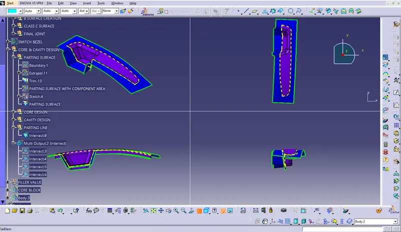
- Yellow dot line shown in figure is parting line.
Core & Cavity:
- The core & cavity are the shaped sections in either half of the mould tool which give the plastic product its final shape.
- The hot molten material is injected into the core & cavity and then sets hard into shape.
- The design of the core & cavity is essential in the correct formation of the product.
- Core is an extended or male portion of the mould which creates the internal plastic part surface
- Cavity is a depression or female portion of the mould which creates the external plastic part surface.
Core creation
step 1
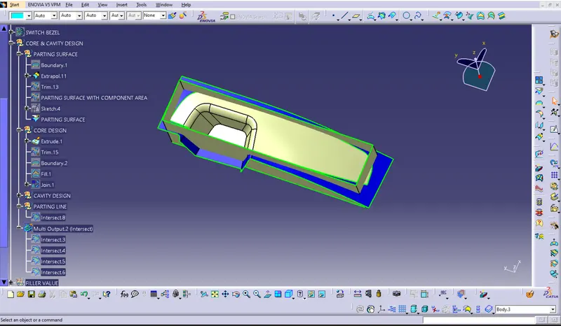
step 2
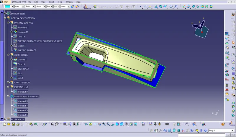
step 3
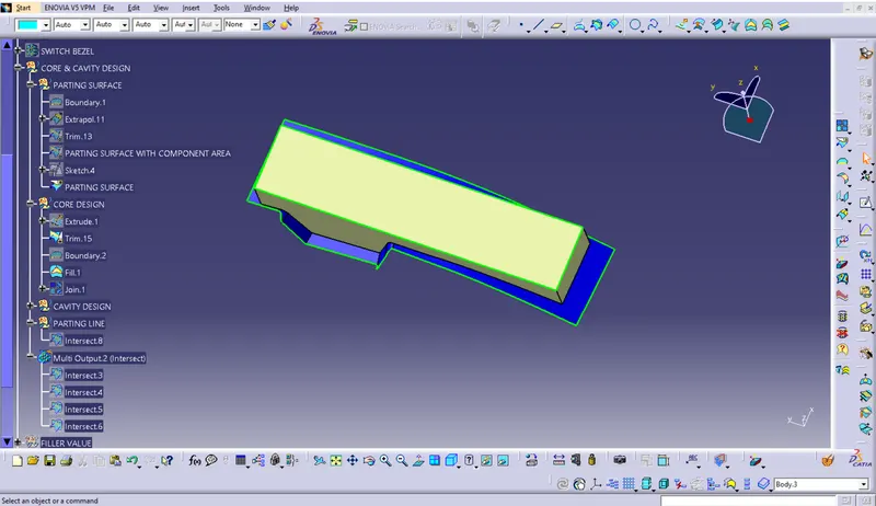
step 4
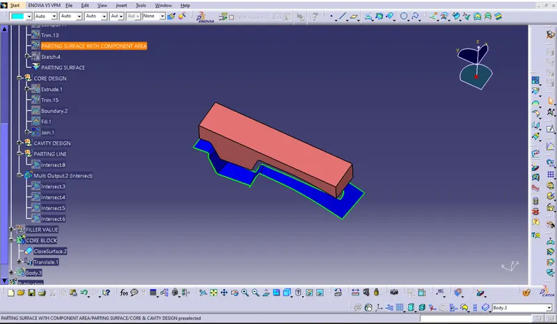
Cavity design
step 1
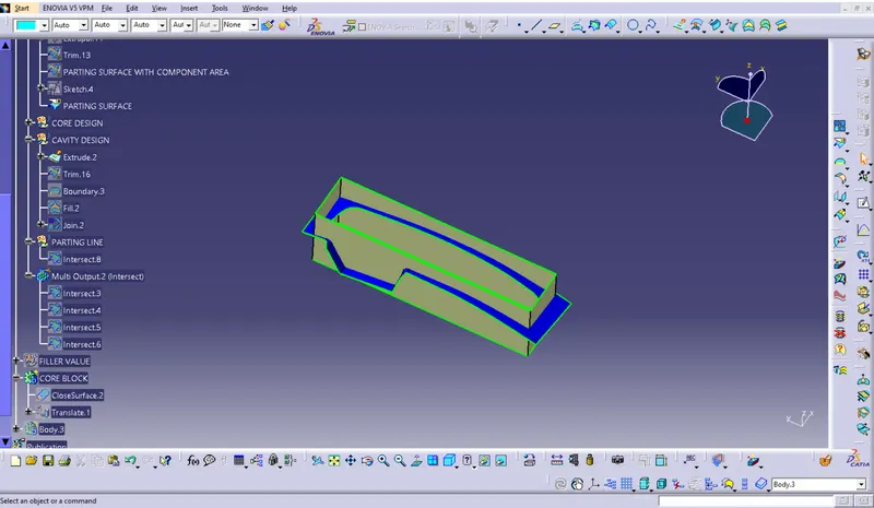
step 2
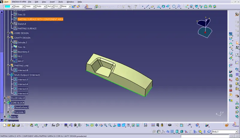
step 3
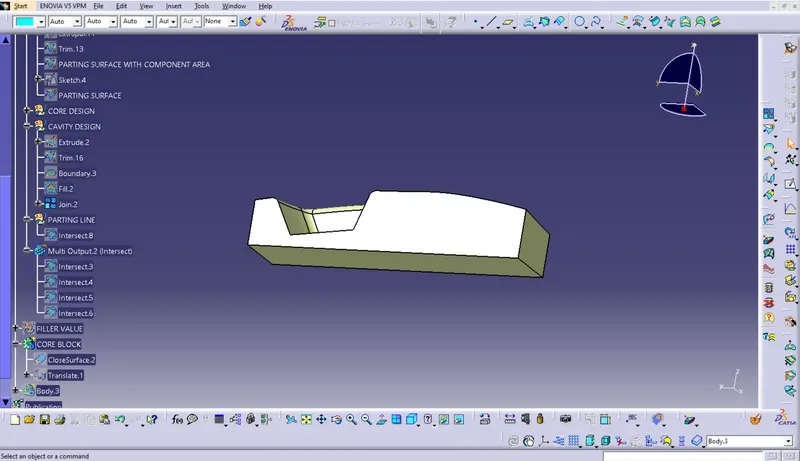
step 4
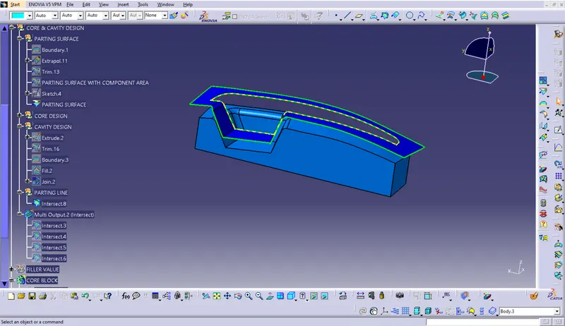
FINAL OUTPUT
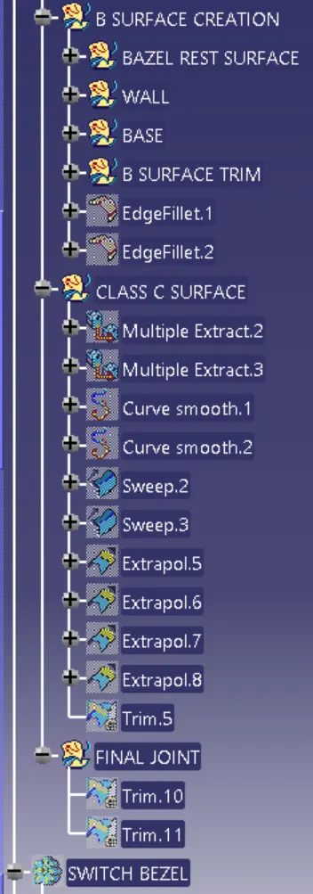
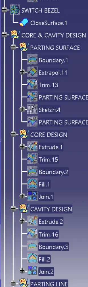
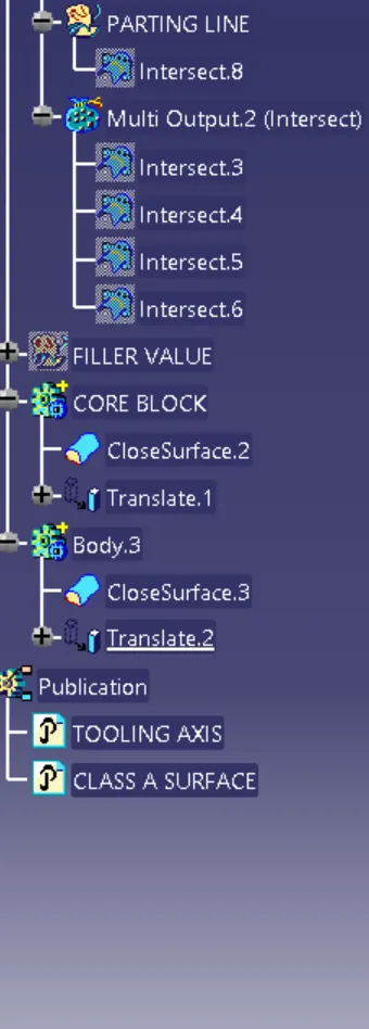
TREE STRUCTURE
CONCLUSION
- Hence the core and cavity blocks from the switch bezel we have already designed as the solid part is created sucessfully. And here we create the parting surface and the parting line. from this Draft analyis and parting surface we try to make the parting surface as flat surface as much as possible which is useful for large number of prodction the part.