Week 8 - Challenge 6 - Core & Cavity Design
AIM:
Create the Core and cavity blocks for the switch bezel designed in the earlier challenge.
CHALLENGE EXPECTATIONS:
- Tree Structure
- Ensure Proper Tree Structure
- Geometrical sets should have a proper name based on the sketches present inside of it
- All the sketches should be created under the Geometrical set
- Use the Close Surface feature to make a solid body from the surface.
- Publications: Use the publication option and publish the below
- Tooling Axis
- Switch Bezel Solid / Surface body
- Parting Line and Parting Surface
The core & cavity are the shaped sections in either half of the mold tool which give the plastic product its final shape. The hot molten material is injected into the core & cavity and then sets hard into shape. The design of the core & cavity is essential in the correct formation of the product.
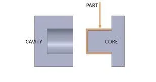
The parting line is a surface that divides the mold block into two parts – the core and the cavity.
In INJECTION MOLDING, the parting line is the line where the two mold halves meet, and the parting surface is the mold surface that forms the boundary between the two mold halves.
A parting surface is a separable contact surface that separates the mold to remove the product and the congealed material from the pouring system. A mold may have one or two or more parting surfaces depending on the need. The parting surface may be perpendicular to the closing direction, or parallel or inclined to the closing direction.
The parting surfaces provide support to the mold during the injection process and help to distribute the molten plastic evenly. It is important to design the parting line and parting face carefully to minimize potential defects in the molded part.
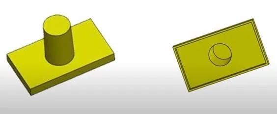
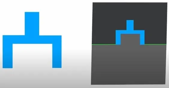
DRAFT ANALYSIS: The major consideration of Draft analysis is whether a sufficient draft angle is provided on the component. Components while designing should be provided with a considerable amount of draft angle depending on the manufacturing consideration. For plastic components, we provide a draft angle of 3 degrees. But for Automotive sheet metal parts, it will be from 7 degrees or more.
TOOLING AXIS CREATION: The direction in which the mold or core and cavity opens is the tooling axis. With the help of the tooling axis created along the X-axis and the Y-axis, these tooling axes are used for creating by bisection method.
Where the two lines and point will be selected as inputs.
PROCEDURE:
- First the class - A surface is checked before creating the Class-B&C surface and finally the solid body must be analyzed. Both can be done by following the below procedures.
- By changing the view mode to custom view parameters - Material mode then the feature draft analysis is enabled.
- Then the compass was activated and placed with the tooling axis by dragging the red pointer and then locking it.
- Then, by selecting the quick analysis mode, the nominal value will be 3 degrees and checked for the component's draft angle.
- The green color area shows that it satisfies the 3-degree draft angle. If not satisfied then by using the Running point tool the area is measured and then altered to get a successful draft for the created tooling direction.
CREATION OF TOOLING AXIS USING THE BISECTING METHOD:- The first thing to do is to find the possible tooling direction by visually checking the part. Rotate the part in all directions and find out the most suitable direction for tooling. Here in this case viewing from Z direction we can clear the face in tooling.
- Then a point on the surface of the part was created, we can create the point anywhere on the surface but usually, we take a CG point or take a point near the center. On this point, we put a new axis system.
- Then, finding the X direction tooling axis by using the intersect command the boundary in the X direction or XZ plane has been projected. The draft line is drawn in the XZ plane.
- Then, finding the Y direction tooling axis by using the intersect command the boundary in the Y direction or YZ plane has been projected. The draft line is drawn in the YZ plane.
- Bisecting lines were used to get the exact medium from the two sides so that a maximum positive draft angle can be achieved.
- Finally by using the bisecting line option the tooling axis was created by selecting the tooling axis x direction and y direction axis.
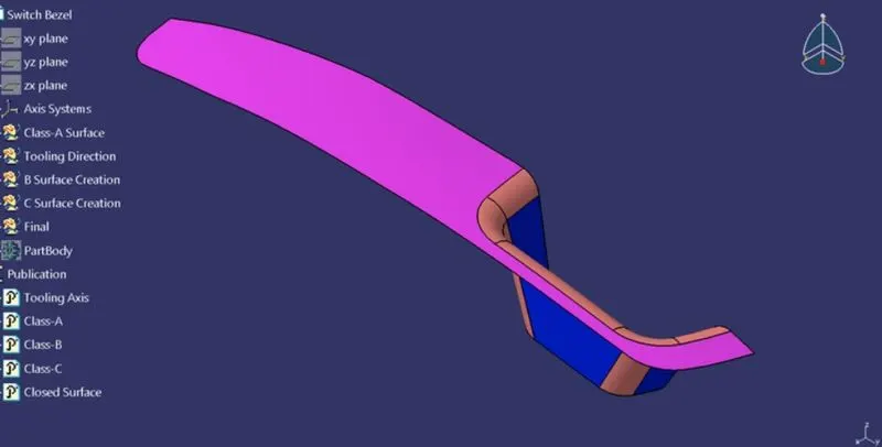
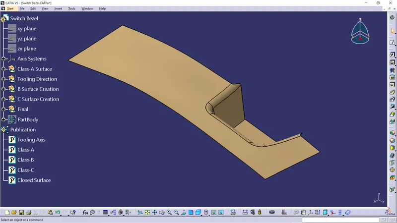
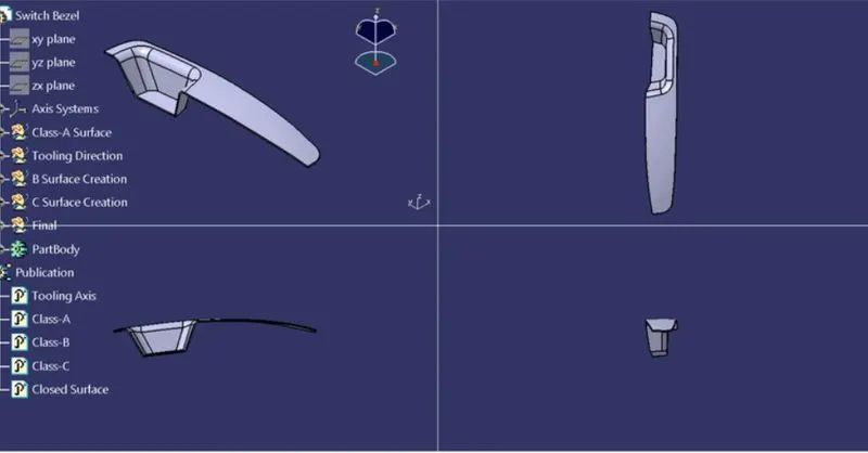
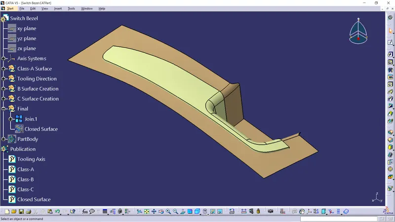
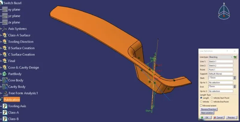
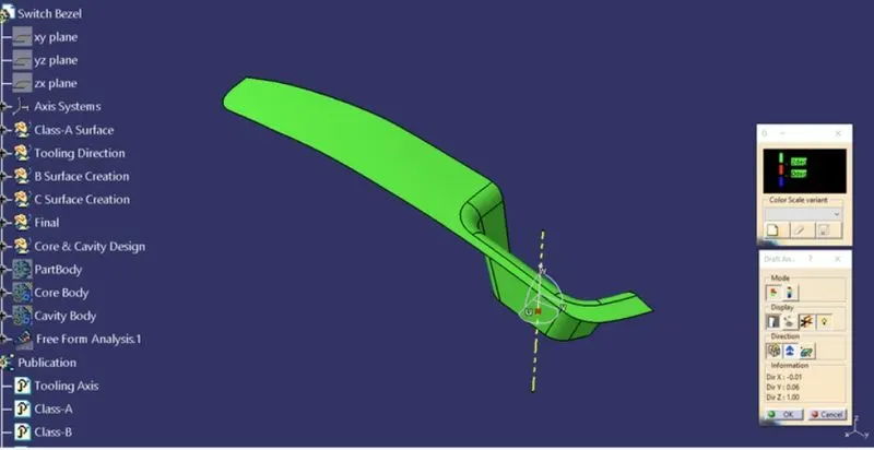
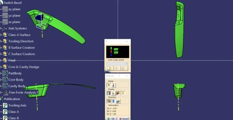
TOOLING AXIS
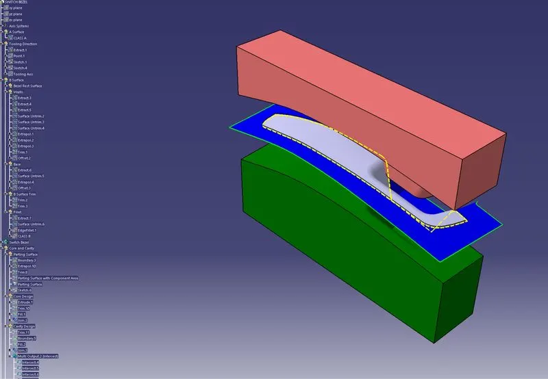
ISOMETRIC VIEW
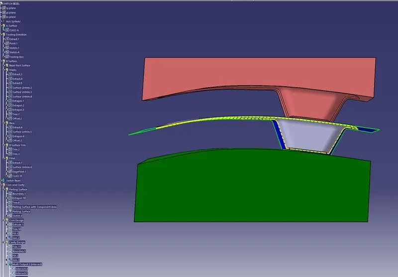
FRONT VIEW
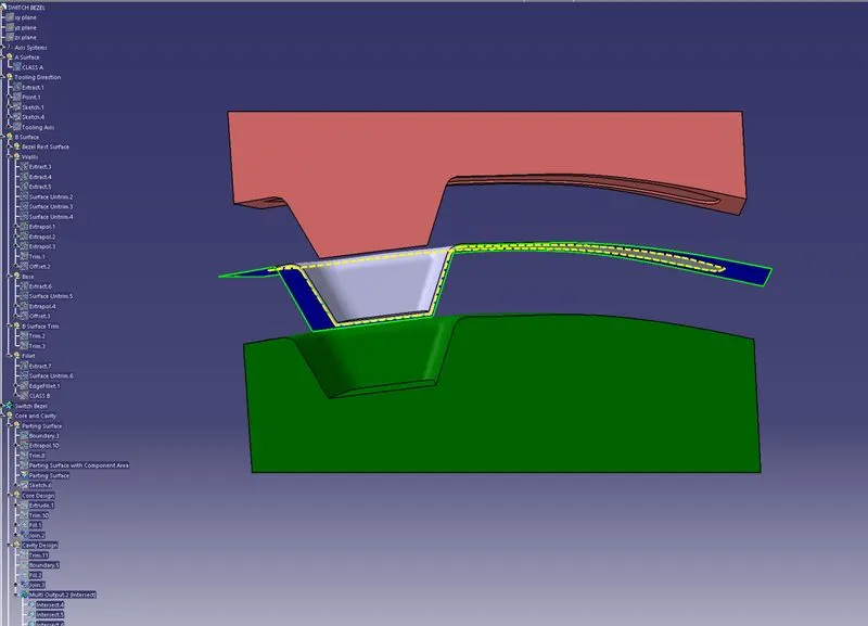
BACK VIEW
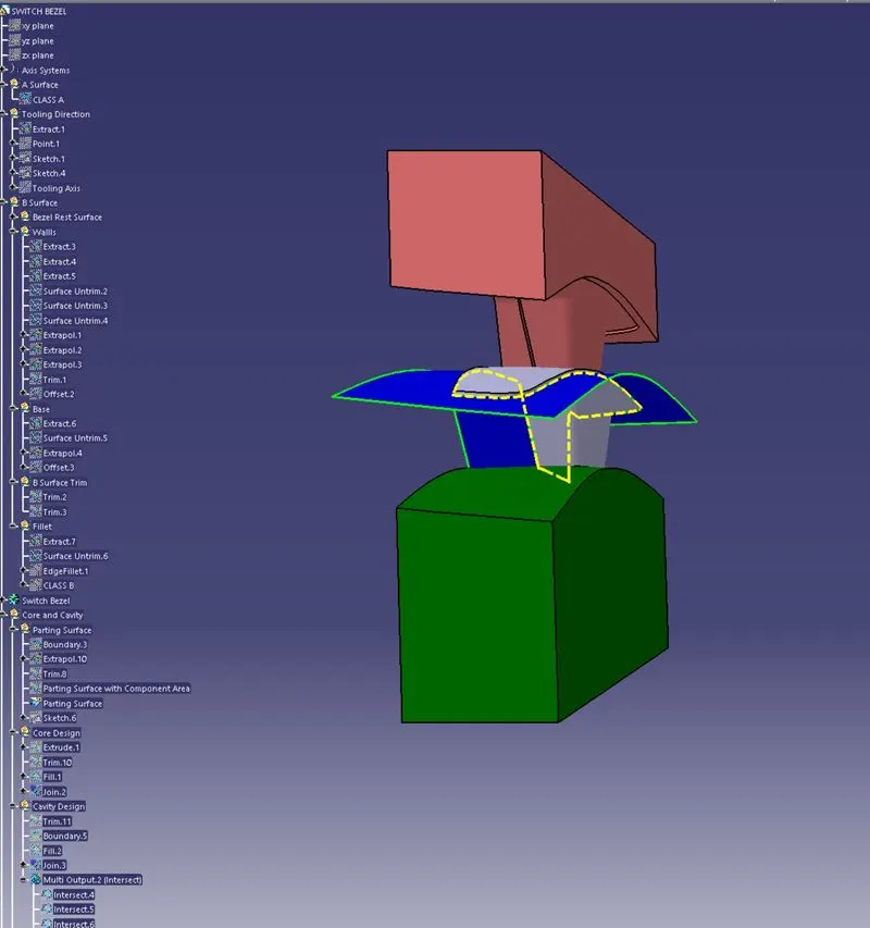
LHSV
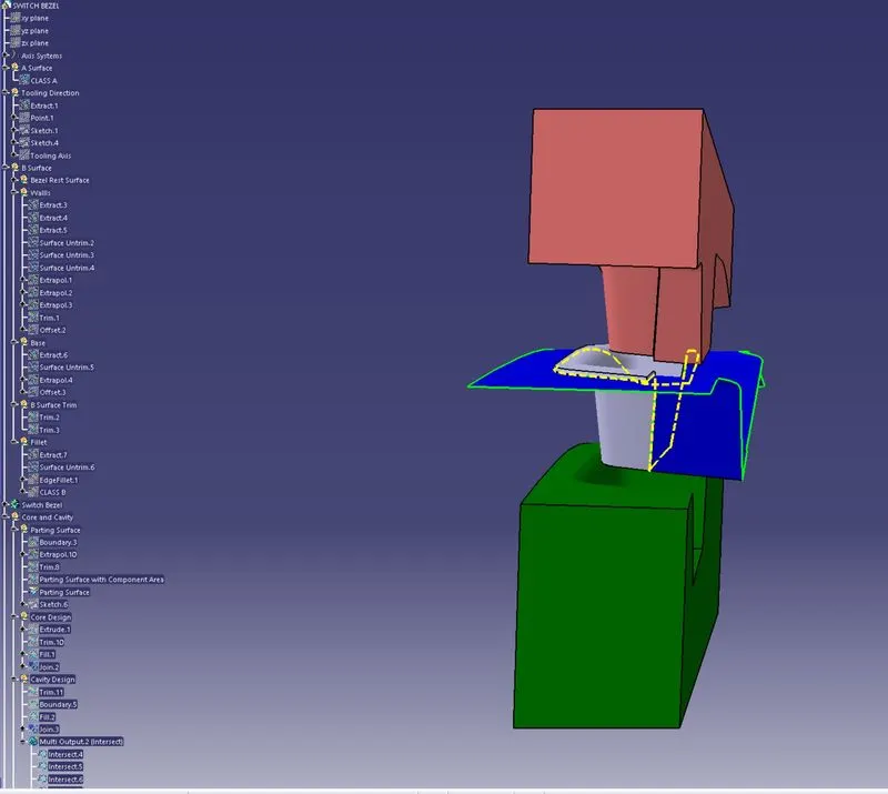
RHSV
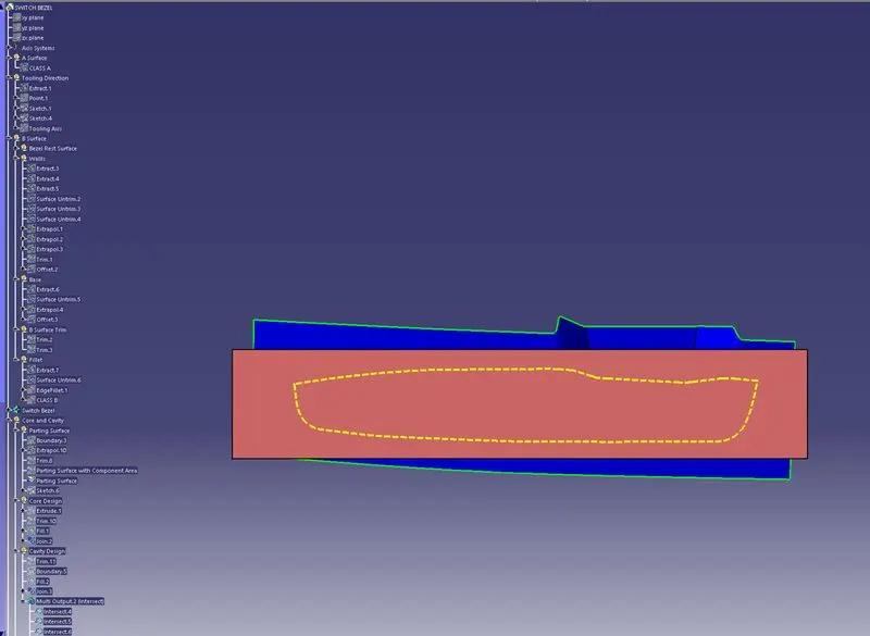
TOP VIEW
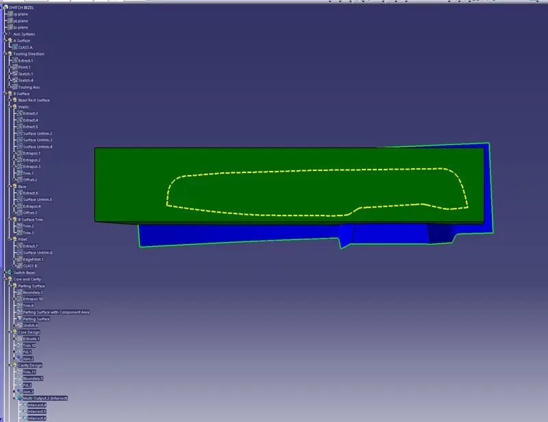
BOTTOM VIEW