DESIGN OF CORE AND CAVITY USING CATIA v5
DESIGN OF CORE AND CAVITY FOR SWITCH BEZEL
AIM: To create the Core and Cavity blocks for the switch bezel designed in the earlier challenge.
OBJECTIVE;
- To Perform Draft analysis for the component.
- To create the Core and Cavity block.
- To create Parting surface and Parting line.
COMPONENT USED;
Switch Bezel
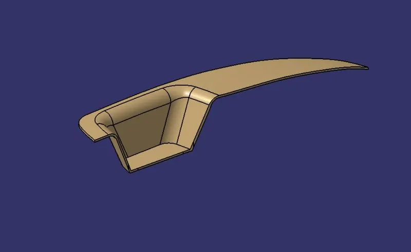
*To continue with the Design procedure first we have to Check the Draft Using Draft analysis Tool.
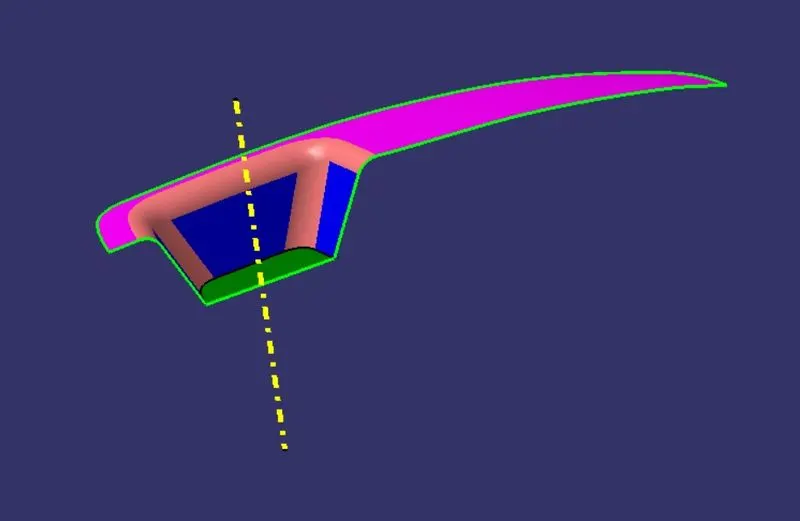
TOOLING AXIS: The Direction in which the mold or Core and Cavity opens is Tooling axis.
PROCDURE;
- In this above Figure we created a point on a class-A surface with the aim to move the main tooling direction.
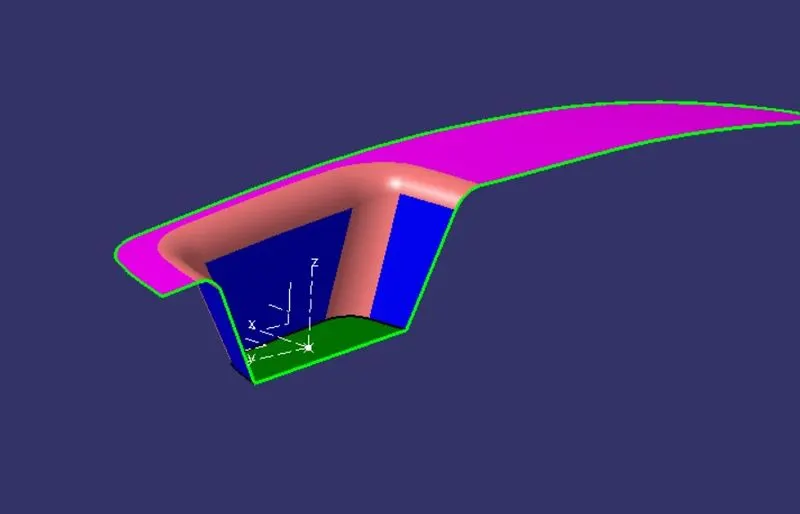
- Created a new Axis support by creating a new point at the centre of the base in Given Class A surface as shown in below image (1)
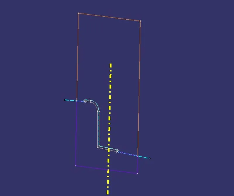
- After creating the new axis support we took the interstions to create a reference lines.
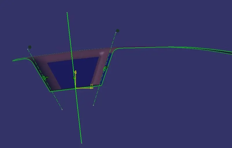
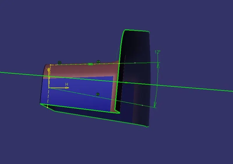
- After creating the intersecting lines select the line command and create two bisecting line as shown in below image (2&3) to create a tooling axis line as shown in above image (tooling Axis).
(Image1)
(Image2)
(Image3)
DRAFT ANALYSIS OF GIVEN COMPONENT :
Draft Analysis:The draft analysis technique is used to analyze whether our part model created in CAD is manufacturable based on the draft condition applied. Here the part should get easily removed from the panel dies (in case of Sheet metal part) or Mold (in case of plastic).
The analysis is done for degree draft as shown in below image,
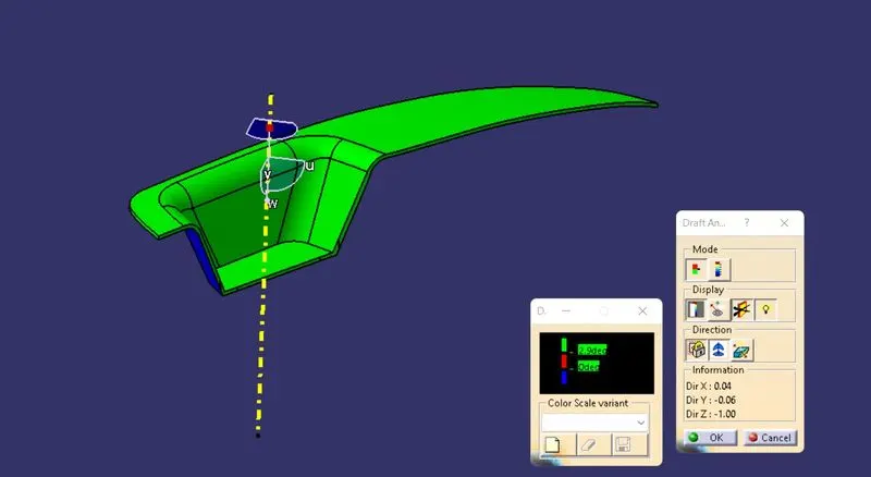
*The yellow dotted line represent the Tooling Axis.
PROCEDURE;
- After creating Tooling Axis select the feature draft analysis option from the insert option,
- Select the element to analyze.
- Click on the compass to define the new current draft direction option and align it with the tooling Axis by dragging the compass to the axis.
- If the colour appears in blue, click the invert button in direction table.
PARTING SURFACE;
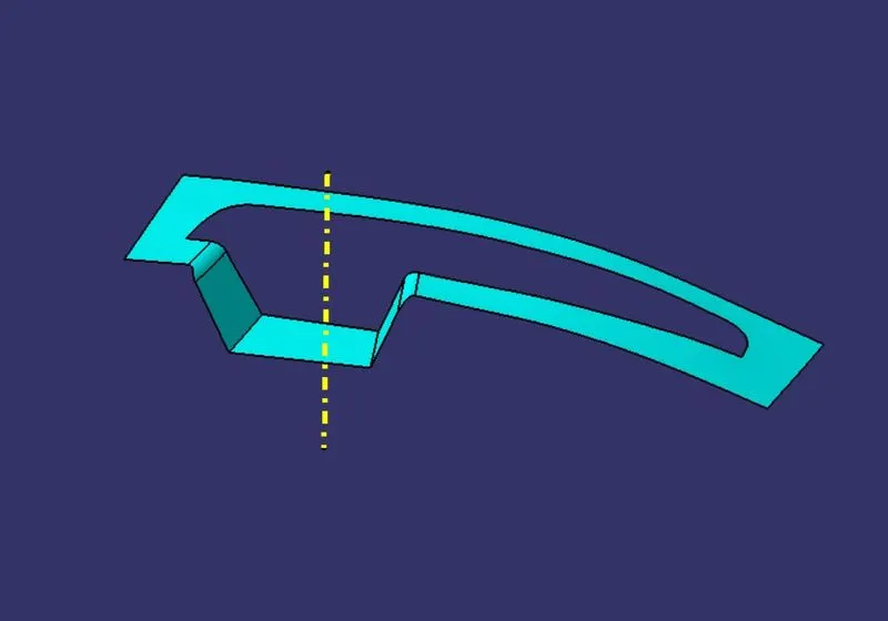
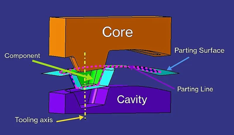
Injection mold has two major components: the movable half and fixed half blocks. During injection molding process these halves are pressed tightly from a sealed hollow to avoid the melt flow leakage and maintain certain holding pressure, the pressed surface called as parting surface, usually parting surface is the biggest projection outline surface of the part.
Parting surface design directly affects the product quality, ease of construction and operation of the injection mold
PARTING LINE;
Parting line are where the two halves of the mold meet. This generally create a physical line on a part that is both visible and noticeable to the touch. These lines however can be hidden or minimized when placed along edges of the part.
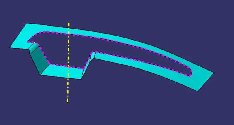
*The pink dotted line represent the Parting Line
CREATION OF CORE AND CAVITY:
CORE;
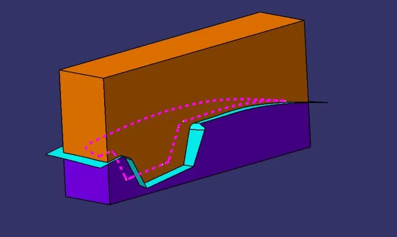
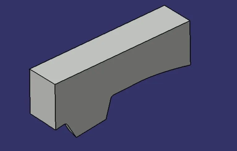
A core is the one part of the mould.and it is responsible for half of the molded part. actually core is the projection of the bodyand cavity is the depression of the body. these core and cavity combines to form a mould. then the plastic material injected into these mould to get a plastic part.
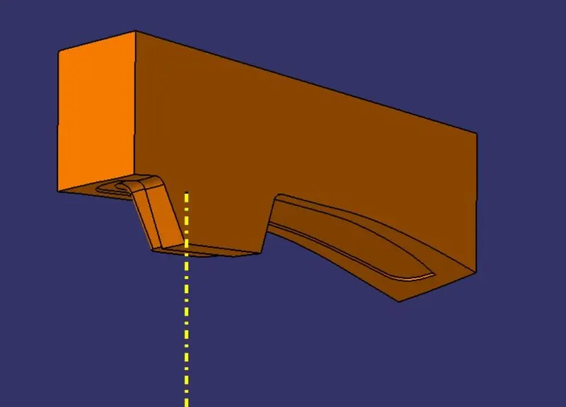
Procedure,
created a new sketch to make profile for core block then extruded.
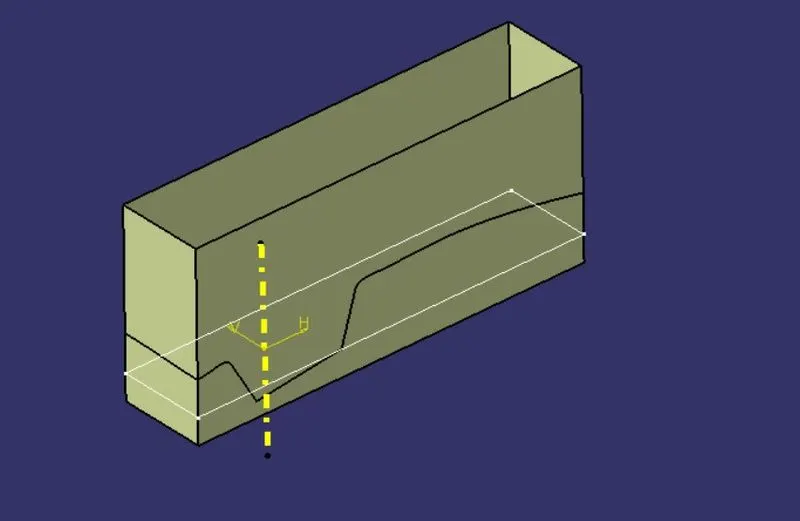
Trimed the surface with class B and extruded surface together.
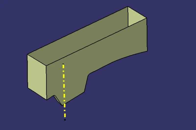
Closed the open profile using Multi-Sections Surface command to create closed Profile surface.
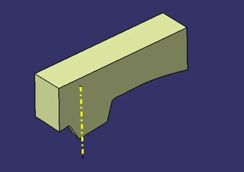
Created a body in part workbench using close surface command to foam a solid body
CAVITY;
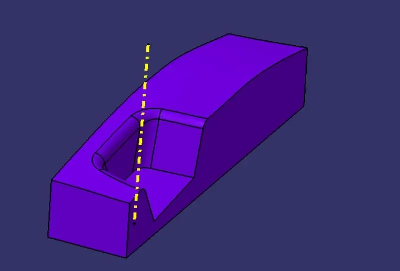
The cavity is the part where the injector and filling of the molten plastic happens. The cavity block is prepared by trimming extrapolated B surface and same profile used in core for rectangular block to extrude along the tooling direction.
The achieved surface is filled and joined to create closed surface as shown picture.
Procedure,
Used the same Extruded surface that we used in Core block Construction.
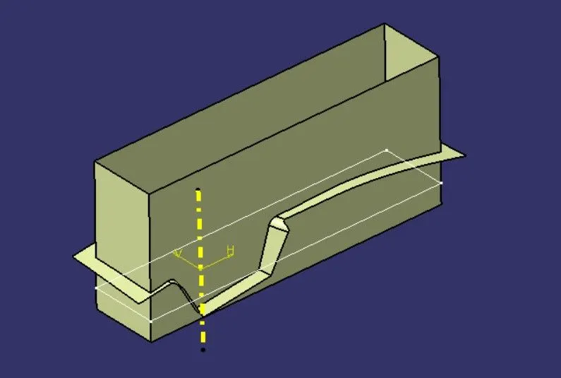
Trimmed the extruded surface with the Parting Surface with component together.
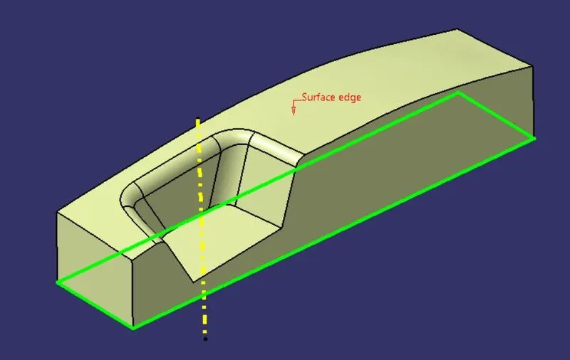
Filled the open boundary using multi-sections surface to create close profile surface
Created a body in part workbench using close surface command to foam a solid body.
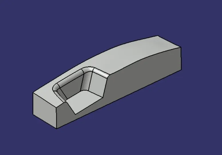
CORE AND CAVITY;
The mold core and cavity are shaped sections in either half of the mold tool which give the plastic product its final shape. The hot molten material is injected into the core and cavity and then sets hard into shape. The design of the core and cavity is essential in the correct formation of the product. The sequence of events during the injection mold of a plastic part is called the injection molding cycle. The cycle begins when the mold closes, followed by the injection of the polymer into the mold cavity. A core is usually made of the best quality sand and is placed into the desired position in the mold cavity. Core prints are added to both sides of the pattern to create impressions that allow the core to be supported and held at both ends
Intersections of the Designs;
VIEWS OF THE DESIGN;
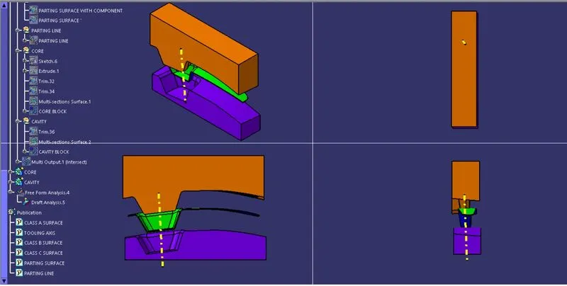
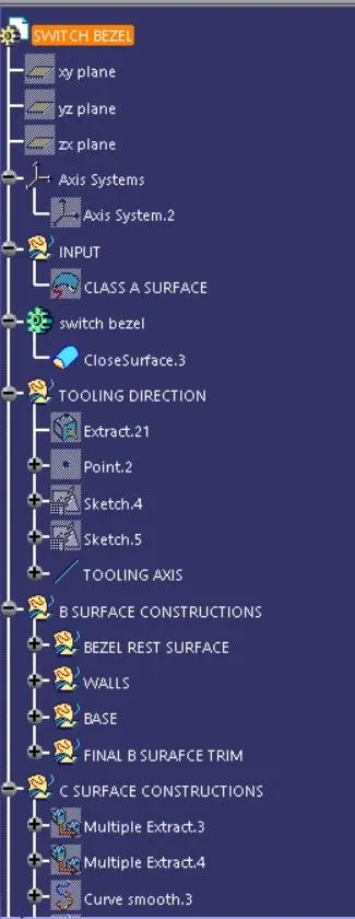
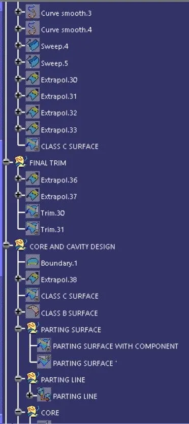
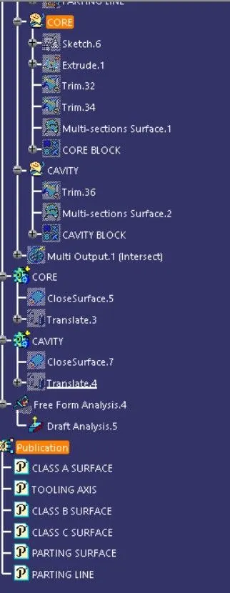
Design Tree;