Week 8 - Challenge 6 - Core & Cavity Design
AIM
To create the core and cavity design for switch bezel
1.TOOLING AXIS
The Tooling Direction is basically the direction that the mold pulls apart. The mold is built in two separate pieces, basically. You have a Cavity side and you have the Core side. The Core pulls apart from the Cavity and that's the Dyeline or the Tooling Direction.
TOOLING AXIS CREATION
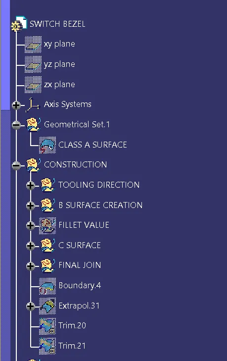
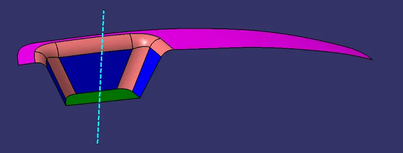
First we have finout the correct direction to see all the views on given class A surface.now we have create new geometrical set nammed as construction first we have extract the base surface on given class A surface.and then to craete point on surface using point on surface command.after creating point we have create axis.using positioned sketch method we have craeating supporting line and then create line on z direction using bisecting line method.we have create another sketch on y direction in the sketch we have draw the horizontal line angle 3 degree.
after complete two sketch now we have craete tooling axis using bisecing method.
2.B SURFACE CREATION
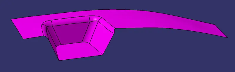
Thickness of A surface is called B surface.Now we have craeate new geometrical set nammed as B surface creation.we have three walls and two base and top surface on given class A surface.
first we have extract the bezel surface and thenuntrimmed extracted surface after untrimmed now we have extrapolt the untrimmed surface.after extrapolted we have offset the surface thickness of 2.5mm.
do the same procedure for other 3 walls and base surface.now trimmed the unawanted surface and then create fillets we get the class B suraface.
3.C SURAFCE CREATION
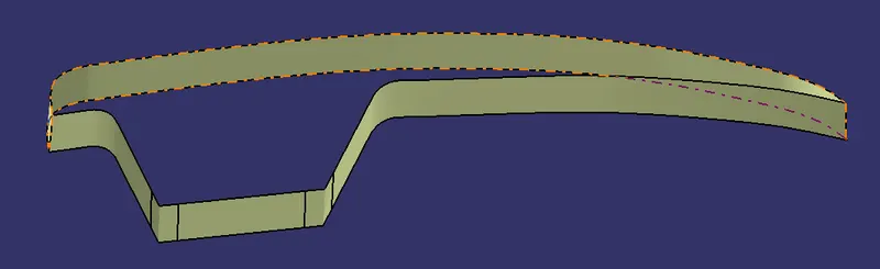
To create new geometrical set nammed on C surface.first we have multiple extract the given class A surface to avoid the patches using curve smooth operation.and then using sweep command to create c surface by using draft direction option
sub type:with draft direction
guide curve 1:curve smooth 1
draft direction:tooling axis
draft angle:3degree
after completing above parameters and the extraplote the open surface and then trimmed we get the c surface.
4.PART BODY CREATION
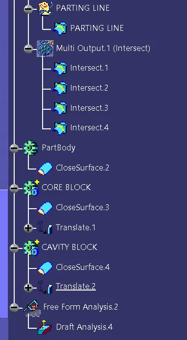
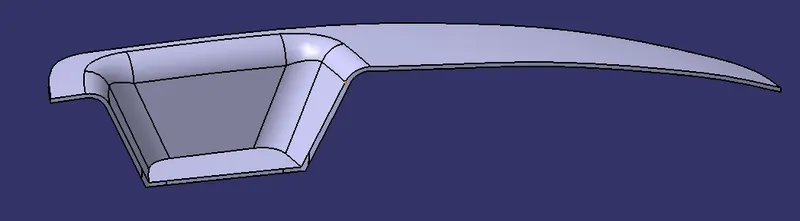
now we have join the both class A surface and class C surface and trim with B surafce we get the close surface.using close surface command we get the solid body.
5.DRAFT ANALYSIS
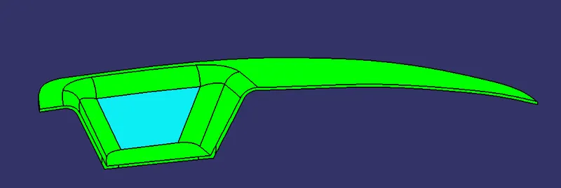
The Draft Analysis allows the user to easily analyze a part for proper draft angle. A Draft Angle describes the amount of taper for molded or cast parts perpendicular to the parting line.after creating solid body now we have analysis the solid body using draft analysis method.feature based analysis command to analysis the part body firstwe have select the composs option then lock the axis and then analysis running pointoption to analysis the surface.
6.PARTING SURFACE
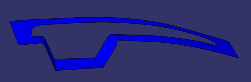
Generally injection mold has two major components the movable halve and movable halve during injection molding process,these have two halves pressed tightly and form sealed hollow to avoid the melt flow leakage and maintain certain holding pressure,the passed surface are called parting surface are the biggest projection outline of the part.
PARTING SURFACE CREATION
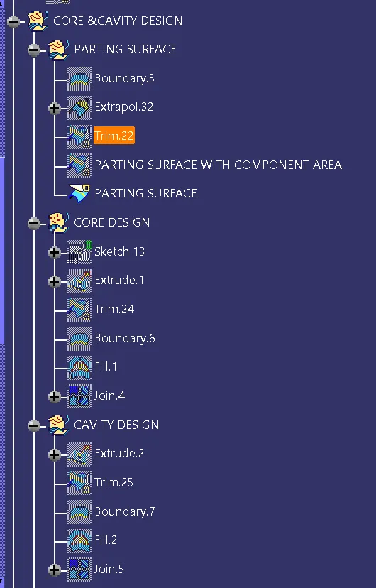
first we have create the boundary on class A surface and then extrplote the boundary after extrploting trim the extraploted surface with class C surface.we get the parting surface.
7.PARTING LINE
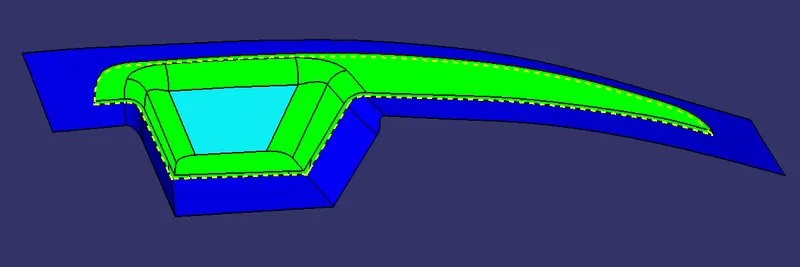
The parting line is where the two halves of the mold meet around the parameter of the part. All parting lines need to seal properly when the mold is clamped in a molding machine.A parting line is an inevitable part of injection molded products. It is the line of separation between where two halves of a mold meet. It manifests itself on injection molded parts as a line that runs the entire perimeter of the part. In most parts, it is just a line that runs straight down the middle.
PARTING LINE CREATION
parting line is nothing but it is the intersection of plastic product and class B surface.
8.CORE &CAVITY DESIGN
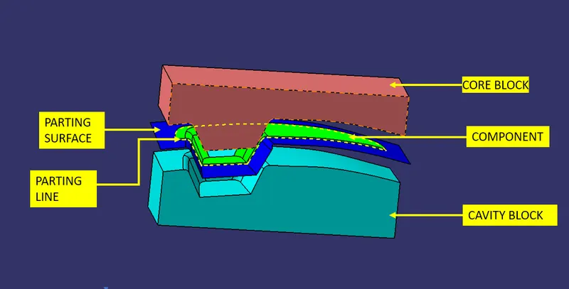
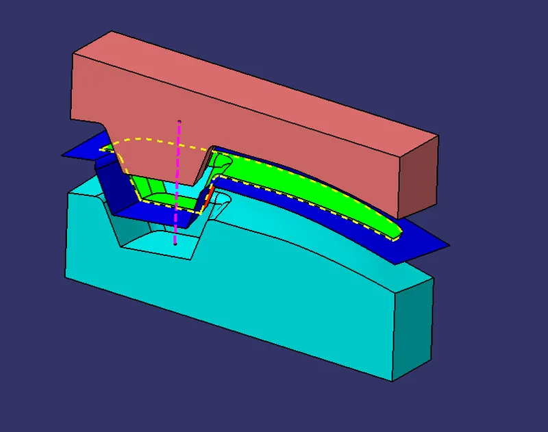
Cavity and core are used in the injection molding process, where the concave part of the mold is the cavity and the convex part is the core. The cavity and core are used in pairs, with the cavity also referred to as the female mold and the core as the male mold.
CORE&CAVITY CREATION
first we have create the rectangle sketch the boundarys are inside the sketch and then create surface extrue on created sketch.next we have trimmed with parting surface with coponent area and then create the
boundary on open surface we have using fill command to close the extrude surface.using closed surface option create the core body.do the same procedure for cavity design.
9.CONCLUSION
finally we have created the core and cavity block design for switch bezel component.
10.VIEWS
FRONT VIEW
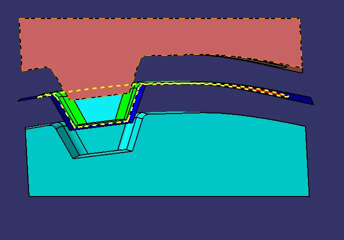
SIDE VIEW
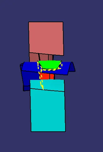
TOP VIEW
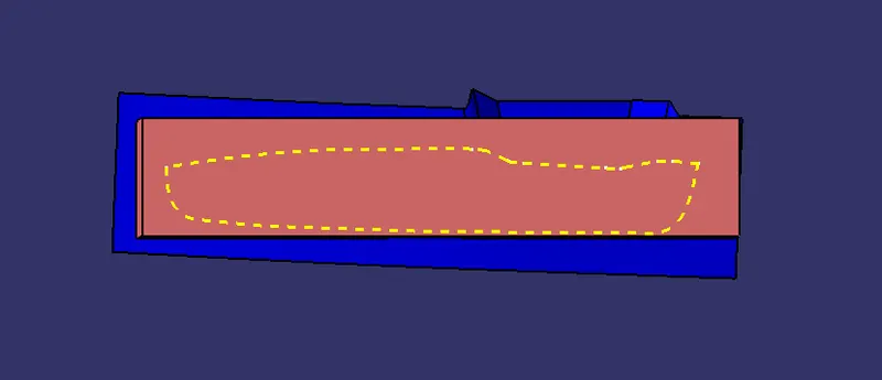
BOTTOM VIEW
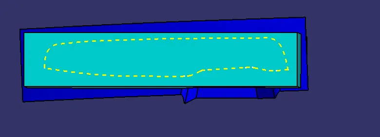
ISOMETRIC VIEW
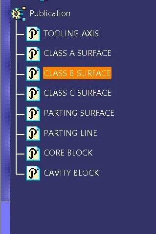
TREE STRUCTURE