Week 8 - Challenge 6 - Core & Cavity Design
Week 8 - Challenge 6 - Core & Cavity Design
Core & Cavity Design
Objective- To Create the Core and cavity blocks for the switch bezel .
Aim-
- Tree Structure
- Tooling Axis
- Switch Bezel Solid / Surface body
- Parting Line and Parting Surface
- To ensure Proper Tree Structure
- Geometrical sets with a proper name based on the sketches present inside of it
- All the sketches should be created under the Geometrical set
- To use the Close Surface feature to make a solid body from the surface.
- To Use the publication option and publish the below
Introduction-
side contains the ejection actuator, which controls the ejector pins. The clamp forces the A and B-sides together, molten plastic is injected into the mold and allowed to cool, the clamp pulls the B-side of the mold away, the ejection pins are actuated, and the part releases from the mold.
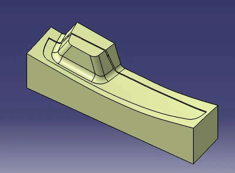
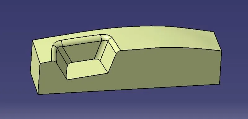
Parting Line:
A parting line, in industrial casting of molds, is the border line in which draft angles change direction. One can check the parting line in the mould or product which divides the two half, i.e; the core and the cavity of a molded part. It is sometimes a starting point for the mold parting surface.
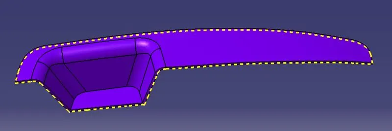
Parting Surface:
A parting surface is a surface that separates the mold block into two parts – the core and the cavity. Image source. Consider a model, as shown in the image above. As you can see, the model is a hollow plastic component. To make a mold for this part, you should first select a parting line for the mold.
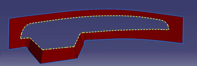
Intersections View:
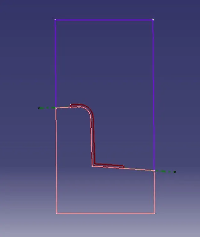
Iso-View: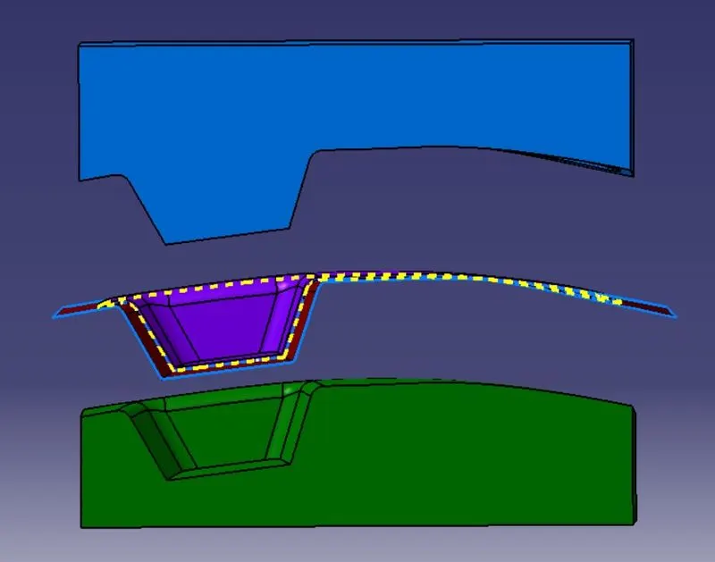
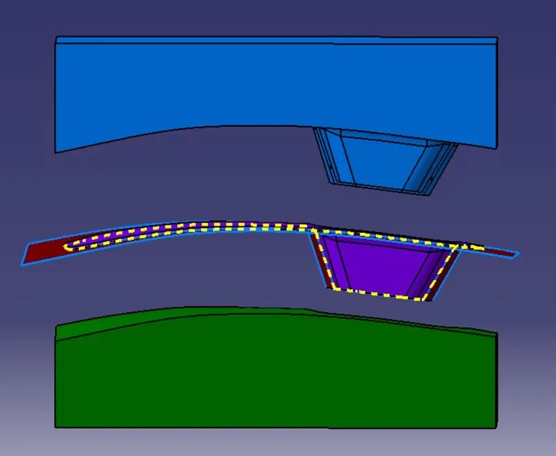
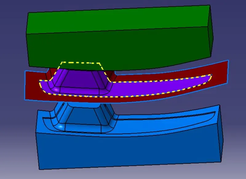
Conclusion:- The model is suucesfully designed as per the design requirements.
END OF REPORT.......