Week 8 - Challenge 6 - Core & Cavity Design
AIM:- Create the Core and cavity blocks for the switch bezel designed in the earlier challenge.
WHAT IS CORE AND CAVITY ?
In a typical injection molding machine, one half of the mold (the A-side) is attached to the fixed side of the press, and the other half of the mold (the B-side) is attached to the moving clamp side of the press. The clamp (or B) side contains the ejection actuator, which controls the ejector pins. The clamp forces the A and B-sides together, molten plastic is injected into the mold and allowed to cool, the clamp pulls the B-side of the mold away, the ejection pins are actuated, and the part releases from the mold.
Let's use a mold for a plastic drinking glass as an example. To ensure that the part stays in the mold half with the ejector system, we would design the mold so that the outside of the glass is formed in the cavity of the mold (A-side) and the inside would be formed by the core of the mold (B-Side). As the plastic cools, the part would shrink away from the A-side of the mold and shrink onto the core in the B-side. As the mold opens, the glass will release from the A-Side, and stay in the B-side, where it can be pushed off from the core by the ejector system.
If the mold design were reversed, the outside of the glass would shrink away from the cavity in the B-side and onto the core in the A-Side. The glass would release from the B-side and stick to the A-side where there are no ejector pins. At this point, we have a serious problem.
At Protolabs, our design staff uses software tools and extensive experience to make the correct A-side vs. B-side choice. On some parts, it is difficult to predict in advance which side of the mold the part will stick to. Well thought-out part design ensures that the part will naturally stick to the correct side of the mold.
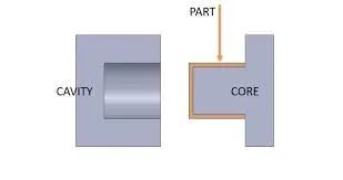
parting line
Selecting a parting line is an important part when designing plastic injection molds. The parting line is the basic element for mold design and manufacturing. A reasonably selected parting line makes the mold manufacturing process easier and quality of plastic parts higher. Otherwise, it will bring trouble to mold making.
In order to remove the plastic part from the mold, and to load the movable core or inserts into the mold body, the mold must be divided into two or more parts. Generally, the mold structure is roughly divided into two main parts: fixed half and moving half. When the mold body is closed, the contact surface of the cavity and core plates makes a parting line.
Usually the parting line of the mold is perpendicular to the mold opening direction of the injection molding machine. When opening the mold, eject or remove the cooled and solidified plastic parts from the mold (or automatically drop), and then remove the debris in the mold cavity, or place the insert to movable core in the mold cavity. The picture shows the basic form of the parting line. The mold opens from A. The fixed half of mold is not moved and the moving half moves and separates. Usually we call the parting line of the moving and fixed molds the main parting line.
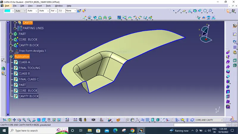
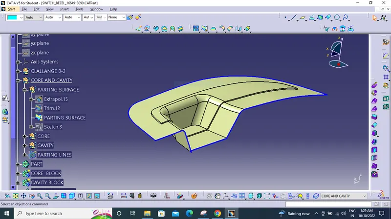
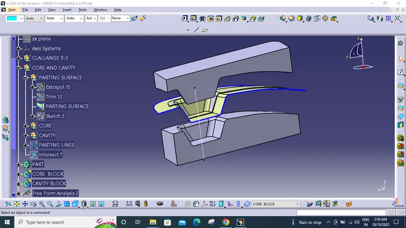
EXTRAPOLATE CLASS A SURFACE THEN TRIM IT WITH THE CLASS C SURFACE AND THEN TO GET THE OUTER PARTING SURFACE TRIM IT WITH THE CLASS B SURFACE.
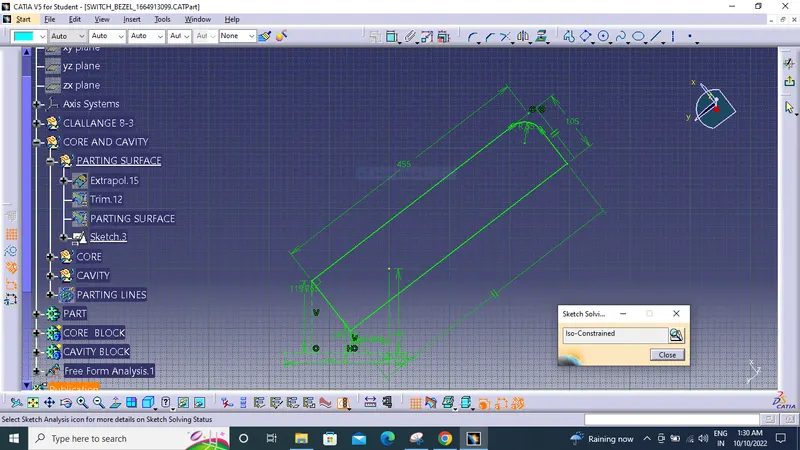
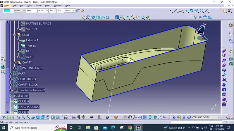
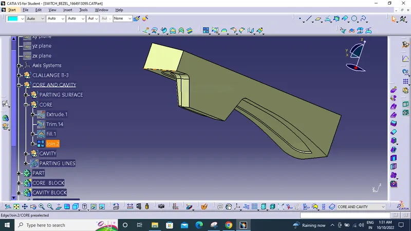
FOR CORE TRIM THE PARTING SURFACE WITH THE EXTRACTED BLUNDEY TO GET THIS BLOCK.
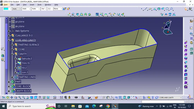
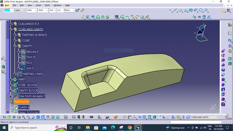
FOR CAVITY EXTRACT THE BOUNDRY AND TRIM IT WITH THE CLASS B SURFACETO GET THIS BLOCK.
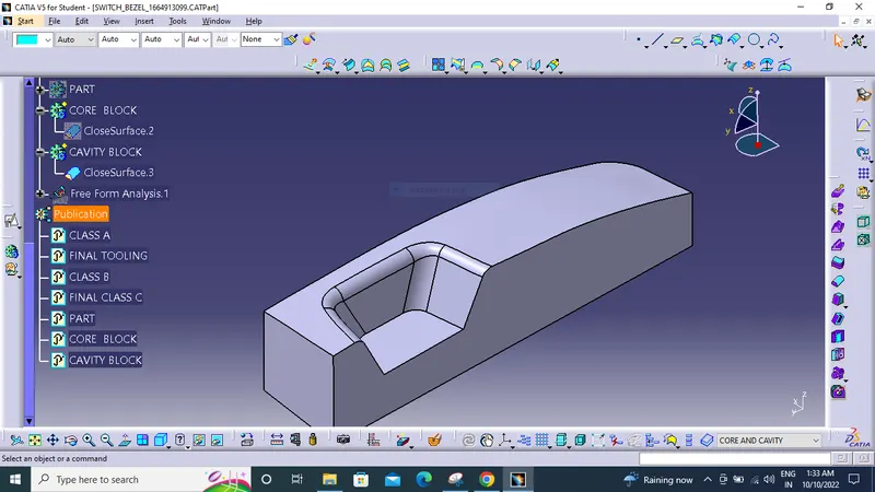
CAVITY SOLID BODY
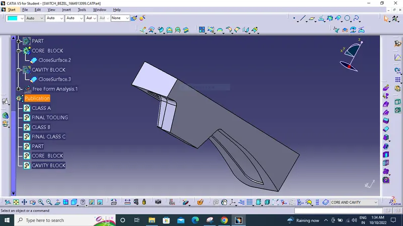
CORE SOLID BODY
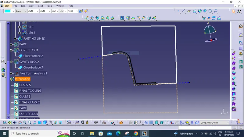
WTHE WHITE PORTION IS CORE BLOCK AND THE DOTTED PINK PORTION IS CAVITY PORTION.
BLACK PART IS THE ACTUAL BODY WHICH IS THE PRODUCT.
THE BLUE LINE IN --- IS THE PARTING SURFACE .
PARTING SURFACE IS WHICH DIVIDES THE CORE BLOCK AND THE CAVITY BLOCK .
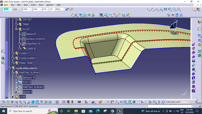
HERE THE RED DOTTED LINE DEFINES THE PARTING LINE
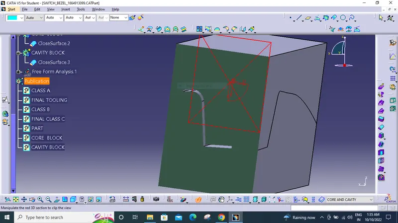
IN THE CENTER THE MATERIAL WILL GOING TO FILL WITH THE INJECTION.
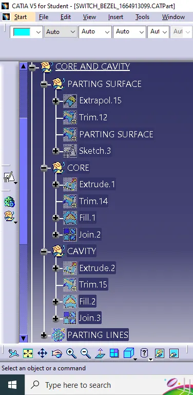
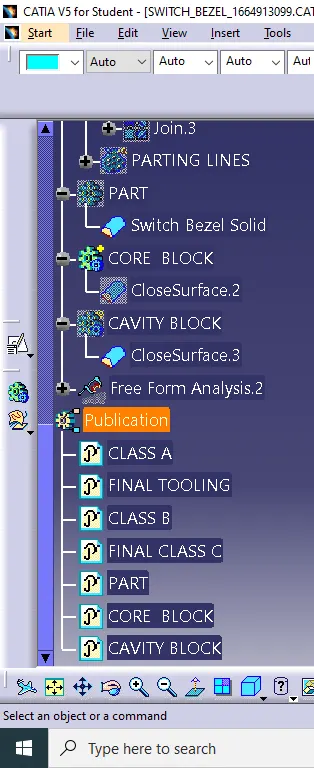
NOW DRAFT ANALYSING
 C
C
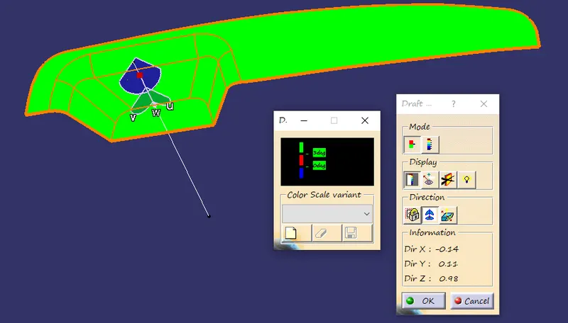
HERE I TOOK THE DRAFT TEST WITH THE TOOLING DIRECTION WHICH IS CREATED ON THE CLASS A SURFACE.
IN MY CASE THE COLOR BOX SHOWS THAT THE SURFACE IS GOOD CAUSE THE DRAFT .
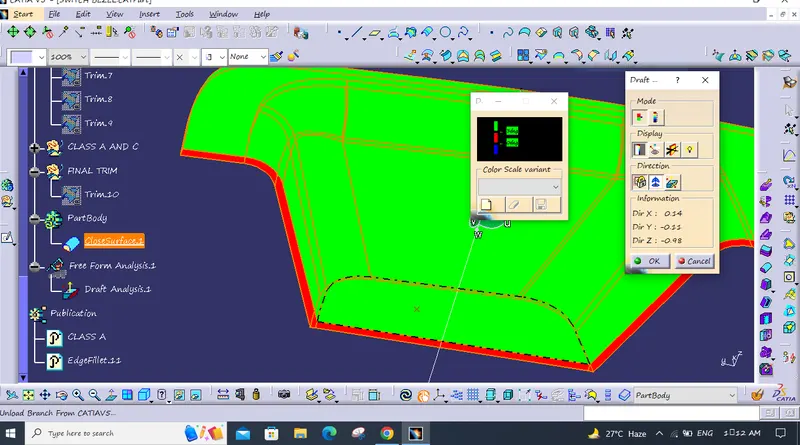
HERE WITH3 DEGREE THE DRAFT ANFLE IS BAD WHICH IS IN NEGATIVE THATS WHY IT IS SHOWING IN RED.
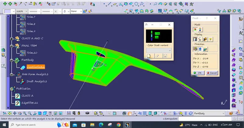
SO HERE I XHANGED THE ANGLE TO 2.9DEGREE. CLOOUR BOX IS SHOWING THAT THE GREEN COLOUR WHICH IS 2.9 DEGREE MY SURFACE IS GOOD WJICH IS A POSSITIVE DRAFT.. {Week 8 - Challenge 2}
THANK YOU