Week 8 - Challenge 6 - Core & Cavity Design
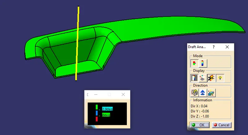
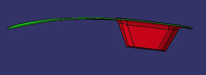
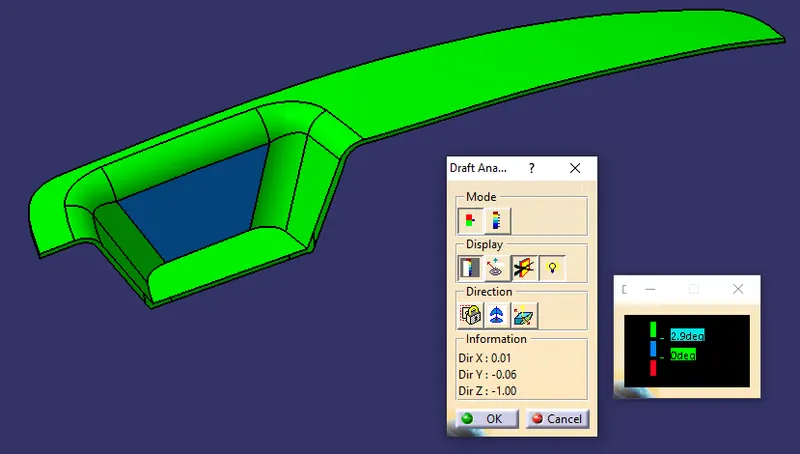
DRAFT ANALYSIS FOR SWITCH BEZEL PLASTIC COMPONENT (Image 1):
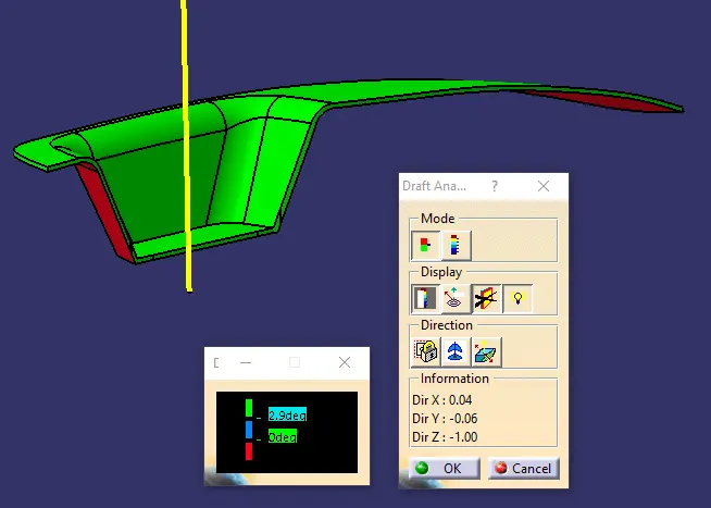
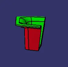
DRAFT ANALYSIS FOR SWITCH BEZEL PLASTIC COMPONENT (Image 2):
To show the bottom side of the switch bezel.
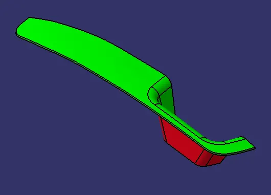
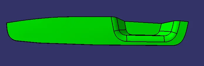
SCREENSHOTS OF SOLID MODEL WITH COLOR CODE IN VARIOUS ORIENTATION:
ISOMETRIC VIEW:
FRONT VIEW:
RIGHT SIDE VIEW:
TOP VIEW:
REPORT
1) DRAFT ANALYSIS:
CLASS A SURFACE:
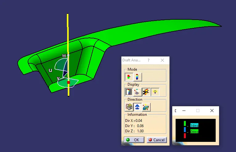
From the draft analysis on class A surface, it is very evident that all the top surfaces are greater than 3 degree.
This is concluded with the green color.
Final Plastic Component:
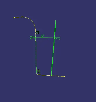
Initially, when i gave 3 degree on the x-axis (zx surface) dummy tooling axis, the draft analysis showed one surface as blue, indicating that the draft is less than 3 degree.
Later, I updated the sketch with an angle 6 degree so that the surface which has draft lesser than 3 degree (blue surface) turned to green indicating the draft is greater than 3 degree. Hence it is feasible to manufacture.
2) TOOLING AXIS:
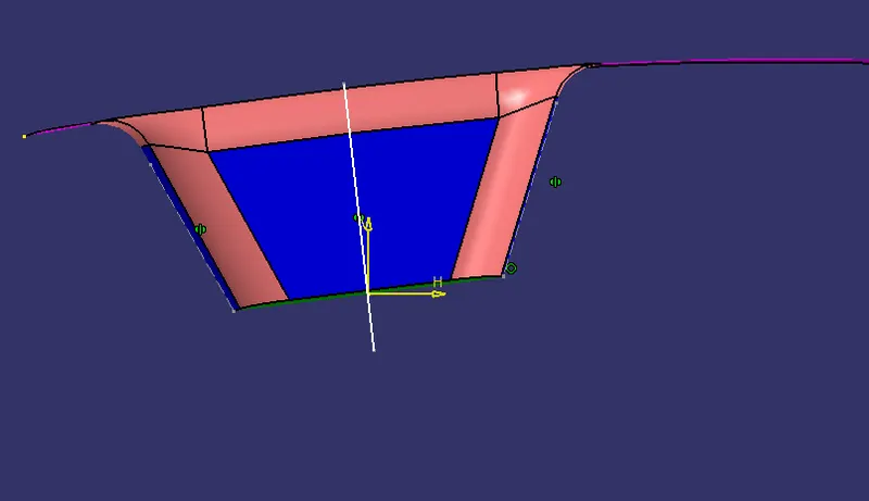
Initially for YZ surface, i created a dummy tooling axis.
I used the walls to create a bisecting line ( Dummy Axis 1).
Same image without Class A surface:
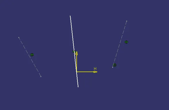
Then for XZ surface, as it contained only one wall, I projected it and then created a dummy axis at an angle of 3 degree initially. Later in draft analysis i found that the surface was in less than 3 degree region.
Hence i increased the angle to 6 degree.
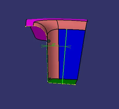
Same image without the Class A surface.
Using the above two dummy axis i create, main tooling axis by bisecting the two dummy axis, which i create initially.
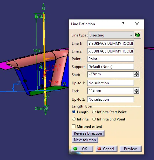
Normal view to tooling axis:
1) All the side walls are visible.
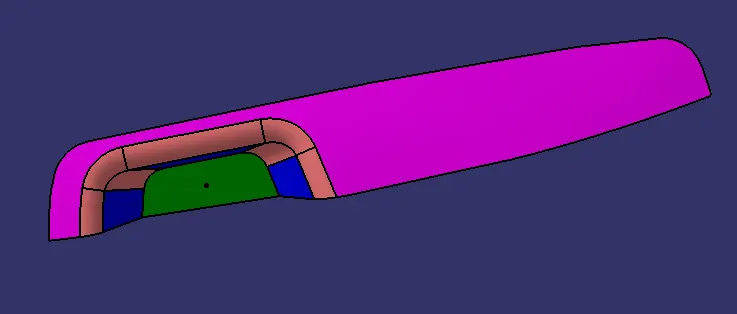
CORE AND CAVITY:
GEOMETRICAL SETS:
CAVITY:
Isometric View:
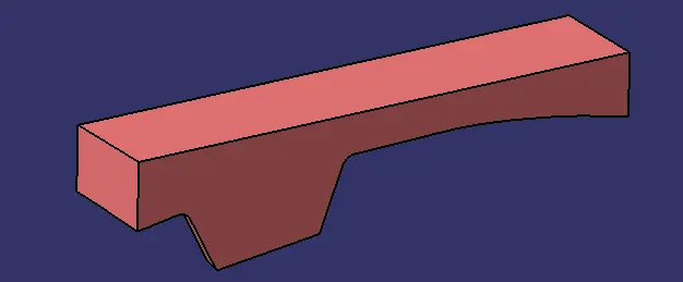
Front View:
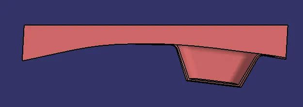
Bottom View:
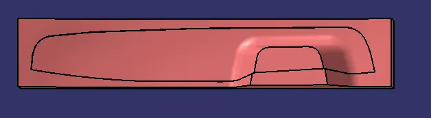
CORE:
Isometric View:
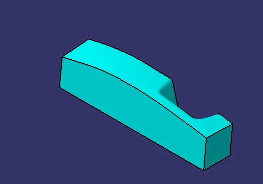
Top View:

Back View:
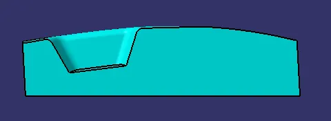
Final:
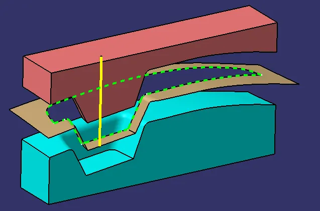
CORE, CAVITY, PARTING SURFACE, PARTING LINE AND TOOLING AXIS
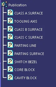
Publications: