Week 8 - Challenge 6 - Core & Cavity Design
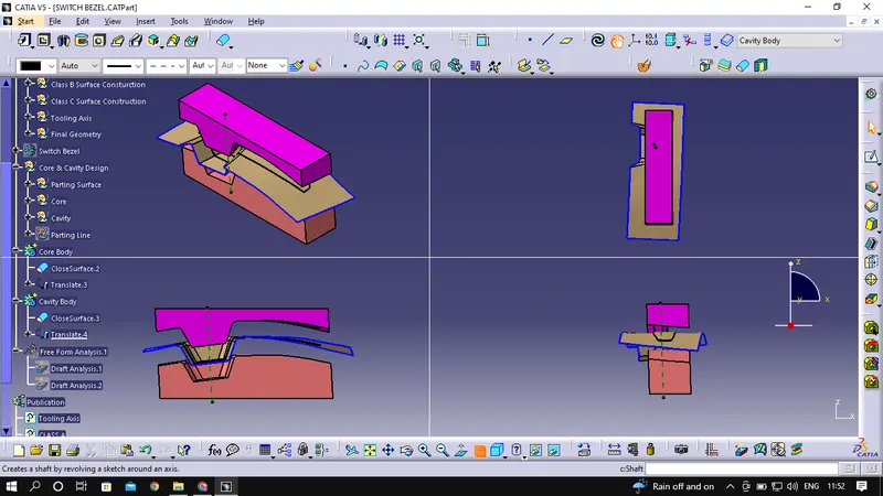
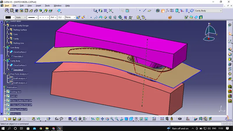
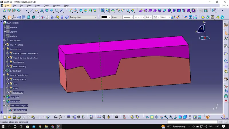
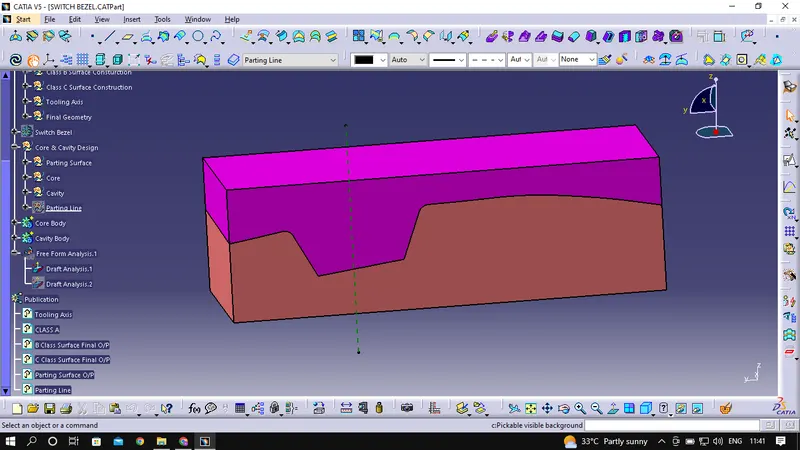
1. Below image represent complete tree structure and publication of Class A, B, Tooling Axis, parting Surface and Partin Line.
2. Draft Analysis of Plastic Component:
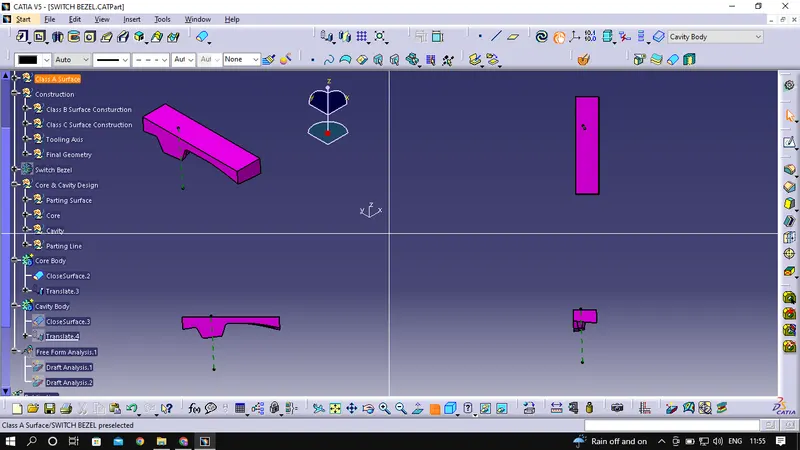
As per given Class A surface, class b and class c surface has been developed. With the help of Class A, B and C surface part has been design by using close body commad.
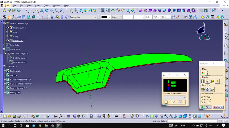
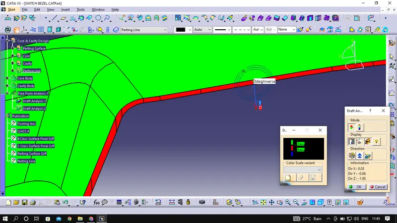
1. To insure the easy removal of the part draft analysis for the part has been carried out. As given in below image all surface on class A is green which mean its ok for plastic injection die moulding and througout the surface at least 3 degree draft maintained which is enough for easy removal of the part. As you can see there is red colour on class c surface, but when you meausre it its showing 3 degree which can be check in below images. It is showing red because the value is near by ~2.98 degree, but that is enough to insure the removal of part from the die. Same tooling axis has been used which was used earlier for class A surface.
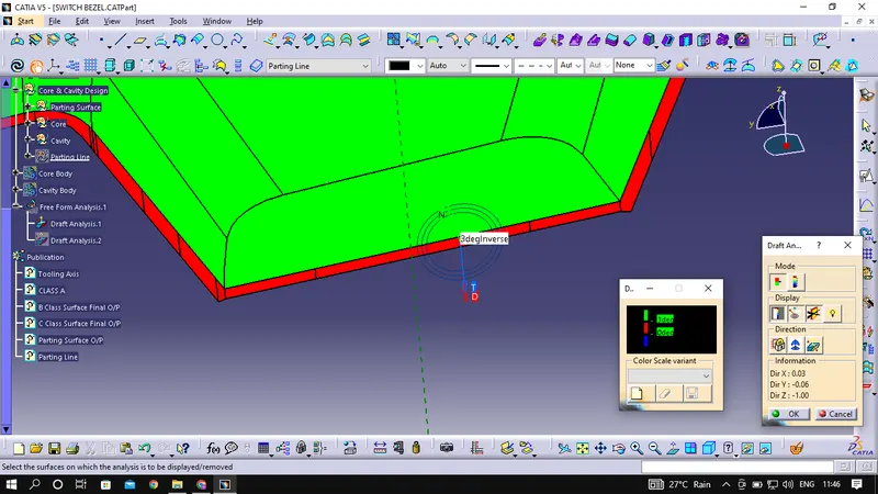
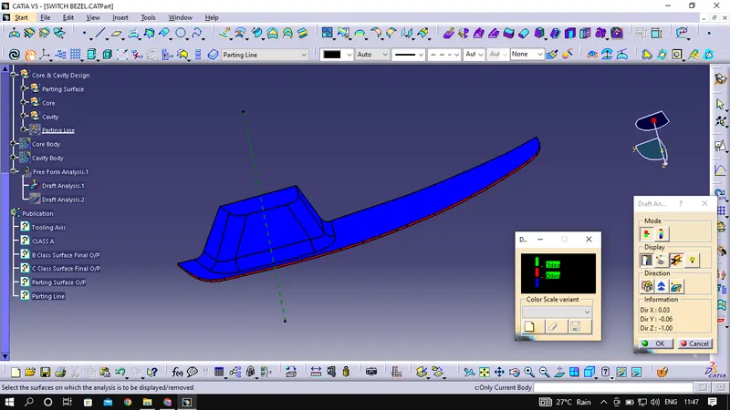
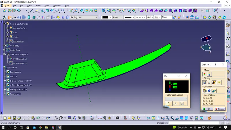
2. Bottom surface showing blue colour which means it has less than 0 degree draft but this surface will be clear from downward direction of lower half part of the die so if i switch the direction which is in next image, now you can seen now its green which means it is good to go further.
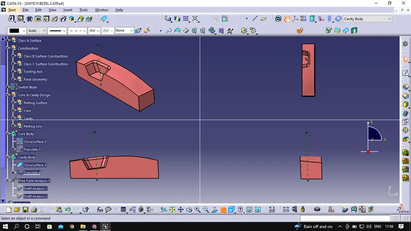
3. Please refer below for all view of core and cavity part.