Week 8 - Challenge 6 - Core & Cavity Design
Aim: Creating the Core and cavity blocks for the Switch Bezel.
Objective: The main objective of this challenge is to design a Core and Cavity for a Switch Bezel' in CATIA V5 with the help of a surface workbench.
Introduction:
The acitivity involves design of core and cavity for Switch bezel component. The Class A, B and C surfaces are used to form Core and Cavity.
Cavity:
Cavity is the fixed half of the injection moulding machine. It consists of runner and gates through which molten plastic is injected into the cavity at high pressure. Cavity side of the component form the Class B surface.
Core:
Core is the movable half of the moulding machine. It moves along the tooling axis. Before molten plastic is injected, it moves into the cavity aided by hydarulic pressure. The same pressure seals core into cavity till the molten plastic is pushed in and cooled down. Then Core disengages with Cavity and the ejector pins within core sub-assembly push the part awasy from core and separate it. Core side of the part is Class-A surface.
Parting Surface:
Injection mould has two major parts: Core and Cavity. These parts are interlocking and form a sealed hollow volume at high pressure where the mould is poured in and thus preventing it to flow out. The surface which the molten plastic touches is the parting surface that seperates the two halves of the moulding machine.
parting line:
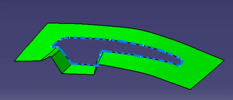
it is the area in which parting surface and component meets Or it is a junction between core and cavity
and the parting surface has some set of rules because the product quality mostly depends on the parting surface.
DESIGN PARTING SURFACE SHOULD FOLLOW THE FOLLOWING PRINCIPLES :
- Design the injection mold simple as possible .Avoid or reduce side parting as much as possible to reduce complexity of the mold making.
- Ease of de-molding as far as possible, for instance the plastic parts should stay in fixed halve of injection mold and should ejected by ejection system avoid , side de-molding action,
- Ensure the dimension accuracy of the molded parts ,Try to make the parts similar dimension accuarcy reqirements in same mold to reduce manufacturing and assembly errors .
- Ensure apperance reqirement of molded parts,finish or mismatch usually occurs on parting surface , so the parting surface should not be designed on high quality requiremnent surfaces.
- Ensure adequate venting.If possible parting surface should be place at the end of the mold flow.This is going to be advantage of fillng and venting.
Draft Analysis:
A draft is an angle at which the part is tapered for easy ejection from the core and cavity block.
Draft analysis is a technique used to analyze whether the drafted CAD model is manufacturable with the given draft conditions. The tooling axis (the direction in which the mold is ejected) is provided so that there should be a smooth ejection of the surface/part from the Core-Cavity block.
CREATION OF TOOLING DIRECTION
- Considering the Ejection from the cavity of the mould after manufacturing the interior trim (switch bezel) must have the nominal 3-degree draft angle.
- Hence the tooling direction is created by considering the above factor and bisecting method is used.
- The base surface of the class – A was extracted and a point at the centre is created and an axis system was inserted to the point with the current feature is disabled.
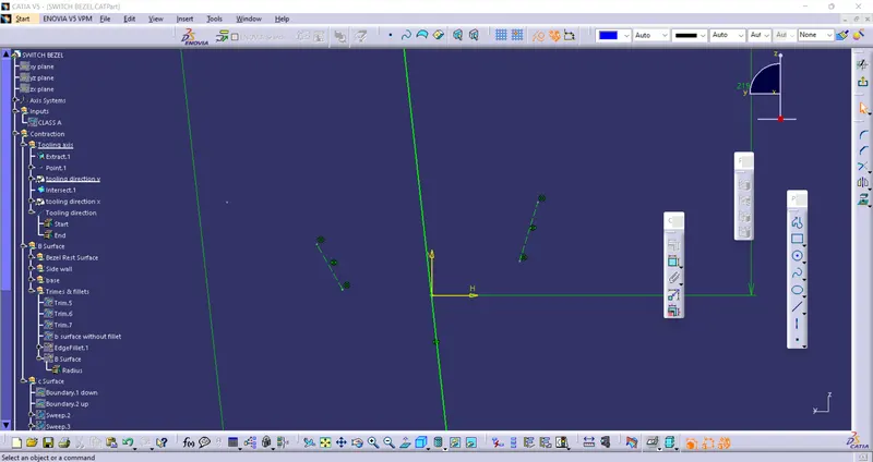
- Then, using project intersection along yz plane is created and the two inclined lines were drawn inside the positioned sketch.
- Then bisecting lines with the two inclined lines were drawn.
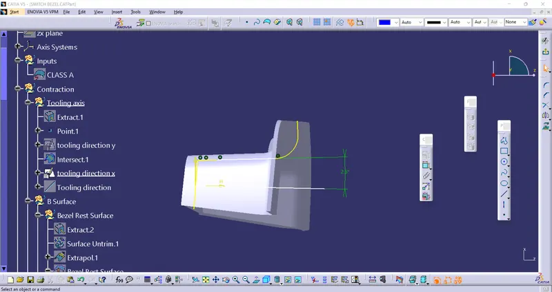
- Now the same procedure is done along the xz plane but on one side we don’t have inclined lines so the centre point is used to extrude a line along the z-direction and gave a measurement of 5 degrees (Tentatively).
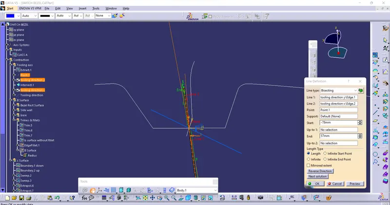
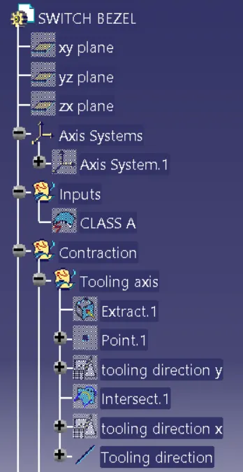
- With these two lines from sketches 1 and 2, the bisecting line is crated and published as Tooling Axis(tooling direction).
Along Y Axis
Along x Axis
After taking baisecting line from X and Y To get main Tooling line
Parting surface creation:
1. Extrapolating the Class A-surface for about 15mm in all directions, so that this can easily trimmed
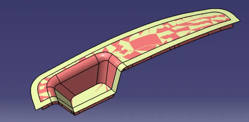
2. Trim the extrapolated part with the Trim.14 and the resulting surface is the parting surface.
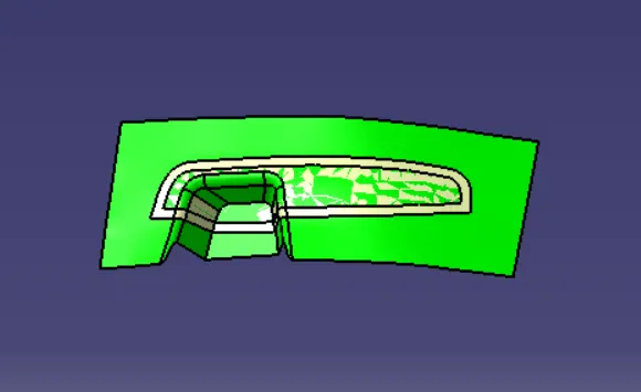
Core design:
1. Plane XY is selected and the direction the axis for 2D Sketch workbench for design core block
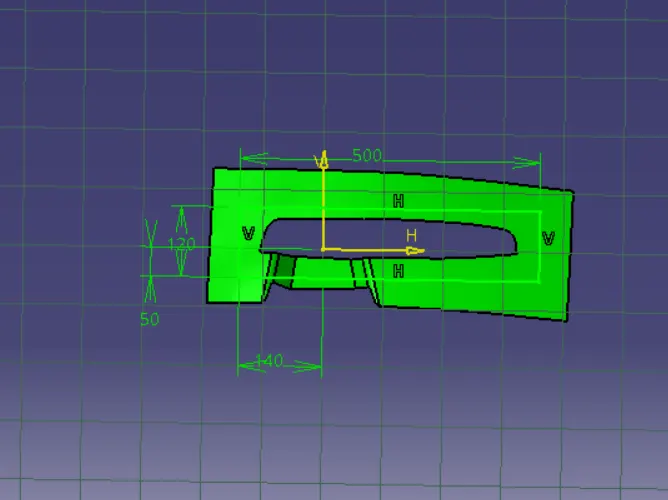
Exluted with the tooling axis
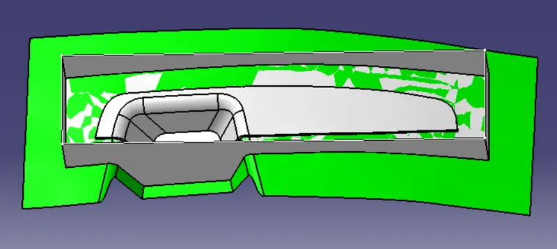
Fill the exluted with boundary command
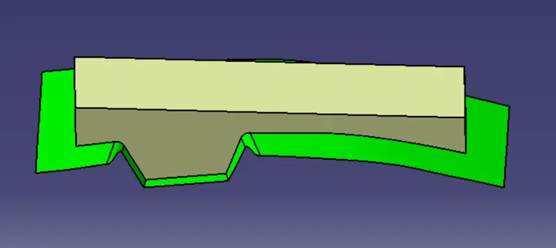
Cavity Design
Similarlly,Repeating the same as done for the cavity part and trim it on other side surface
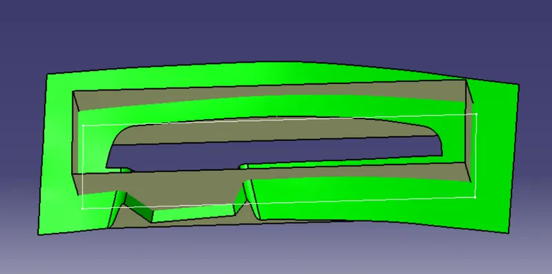
part body of cavity
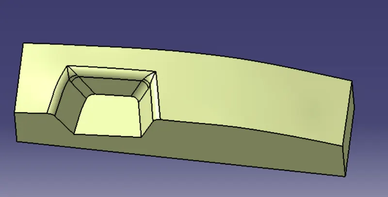
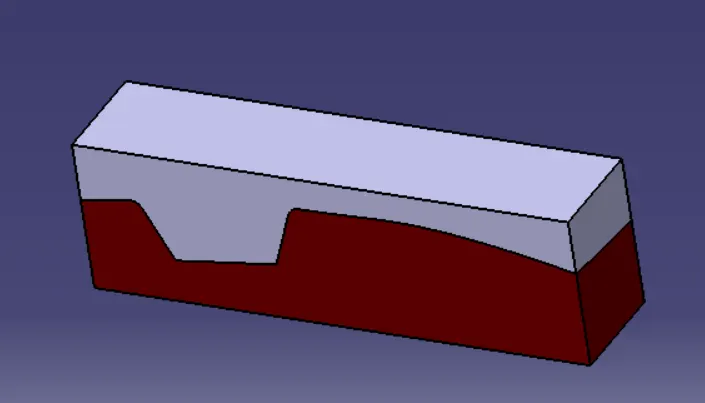
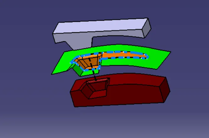
FINAL Close body surfaces of Core & cavity are,
parting surface and parting line
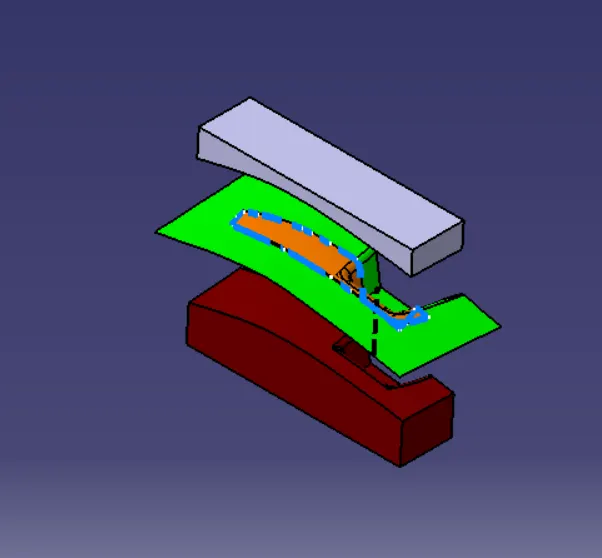
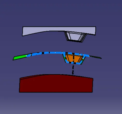
the core and cavity are translated to the certain value for understanding
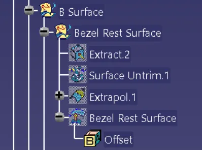
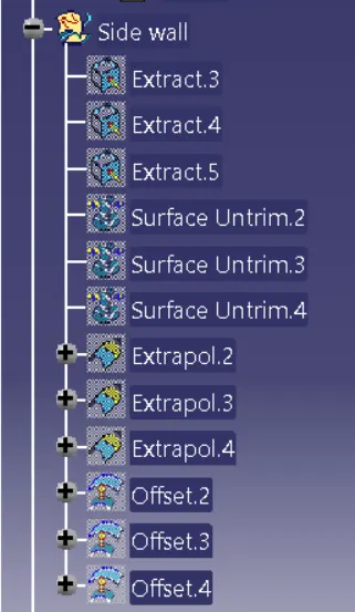
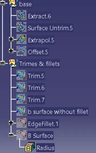
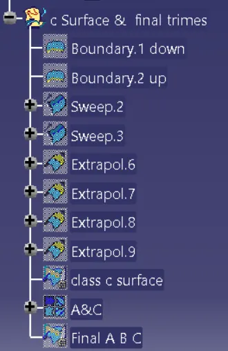
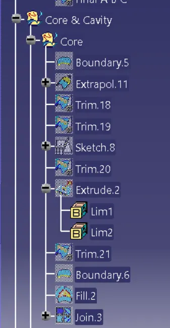
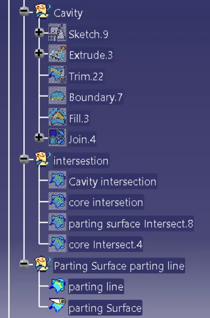
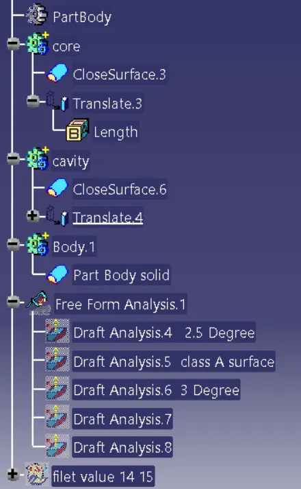
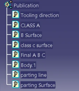
Tree Structure
Drawing View
ISOMETRIC VIEW
FRONT VIEW
SIDE VIEW
LEFT SIDE VIEW
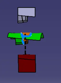
RIGHT SIDE VIEW
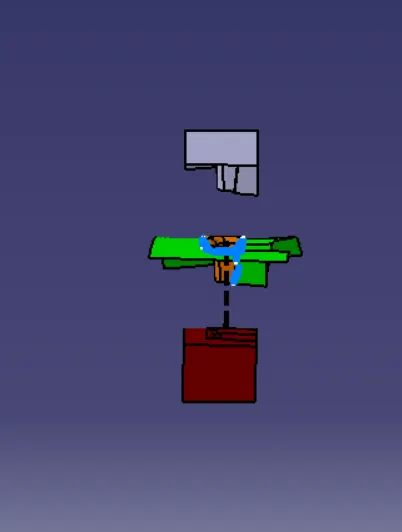
TOP VIEW
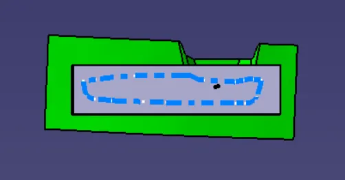
Result:
The core and cavity for the switch bezel has been created as per the design rules.