Week 8 - Challenge 6 - Core & Cavity Design
AIM:
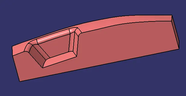
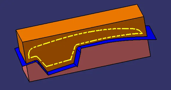
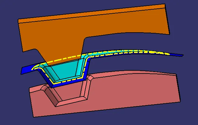
To create the Core and cavity blocks for the switch bezel.
PROCEDURE:
CREATION OF TOLLING AXIS:
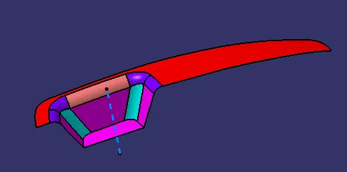
- To create the tooling axis, we need the proper orientation or view that gives the correct features and draft available in the component.
- So here the component view from the Z direction gives the proper view for the tool to see the features present in the geometry.
- To create the tooling axis from the Z direction we need the tooling axis from the other X direction since it gives the draft available at the slanted part.
- The tooling axis created from the X direction by following steps
- The base surface is extracted.
- Then the center point is created using the point > on the surface at 0
- At the point created the axis system is created
- After that switching the view of the model to the X direction and creating the tooling axis.
- Using the intersect in ZY plane to get the boundary lines.
- Then the lines are created along the slant surfaces.
- Then these two lines are bisected to get the tooling axis for the X or the final
- Next, switching in the Y direction and intersecting the switch bezel part in ZX direction to get the intersecting lines.
- Using the axis center point, a line is drawn in sketch mode and it is constrained at the angle of 4 degrees. (this angle value is an arbitrary value and can be changed to get the final tooling axis that provides a positive draft )
- At last, both the lines are bisected to get the final tooling axis.
DRAFT ANALYSIS OF PLASTIC BODY:
Draft Analysis:
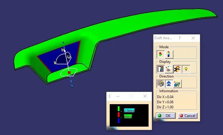
- Go to the Insert menu and select the Analysis option.
- Select Feature Draft Analysis.
- Select the Material option and select the surface.
- Drag the compass and place on tooling axis.
- Make sure that the top surface is in green colour as draft angle should not exceed 3deg.
- Click on Okay after confirm the model.
CORE AND CAVITY DESIGN:
The Mould Core & Cavity are the shaped sections in either half of the mould tool which give the plastic product its final shape.
The hot molten material is injected into the core & cavity and then sets hard into shape. The design of the core & cavity is essential in the correct formation of the product. The sequence of events during the injection mould of a plastic part is called the injection molding cycle.
The cycle begins when the mould closes, followed by the injection of the polymer into the mould cavity.
A core is usually made of the best quality sand and is placed into the desired position in the mould cavity. Core prints are added to both sides of the pattern to create impressions that allow the core to be supported and held at both ends.
CREATION OF CORE:
- Extract Boundary from A class.
- Extrapolate the boundary.
- Unhide the C surface.
- Trim extrapolated surface with C surface.
- Unhide class B surface.
- Trim the last trim with class B surface.
- Sketch a rectangle inside the surface and it will be the dimension for the core.
- Extrude the sketch from both directions.
- Trim the extrude with parting surface with component area surface.
- Fill the remaining boundary with the fill surface option and join it.
- Switch to Part Design Workbench, Define Part body to make Core C Surface into a solid component by close surface panel.
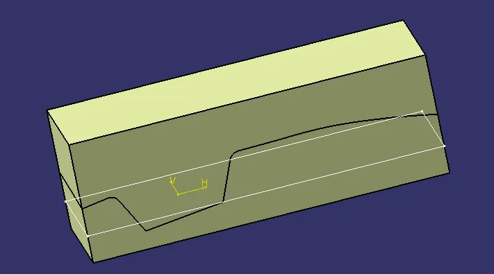
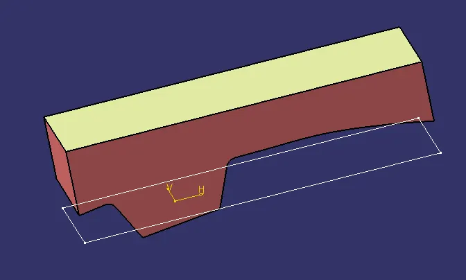
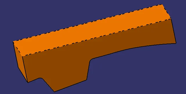
CREATION OF CAVITY:
- The cavity is the part where the injector and filling of the molten plastic happens. The cavity block is prepared by first extruding the outer boundary along the tooling direction.
- This outer surface is trimmed with the B class surface and then it is filled and thickened.
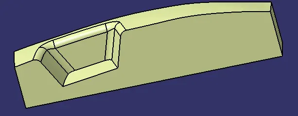
CREATION OF PARTING LINE AND PARTING SURFACE:
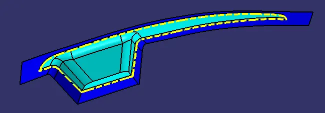
Parting Line : The parting line of a die cast component represents where the two different sides of the mold come together. This line often marks the border between the inside and outside of the part. The location of the parting line indicates which side of the die is the cover and which is considered the ejector
Parting Surface :A parting surface is a surface in the model that you designate to split a workpiece, die block, or another volume. It is designed for the removal of the plastic product and the cold slug, the parting surface is where the core meets the cavity, and usually located at the largest section of a product.
FINAL CORE AND CAVITY:
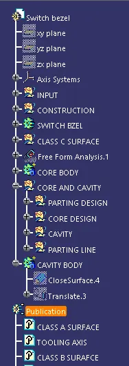
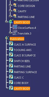
FINAL TREE: