Week 8 - Challenge 6 - Core & Cavity Design
CHALLENGE 26 – CORE & CAVITY DESIGN
Aim: Given completed Switch Bezel Design, complete the design of the core and cavity for the switch bezel component.
COMPLETED SWITCH BEZEL COMPONENT
We were provided the completed Switch Bezel as below.

Fig 1 – Original Switch Bezel Component
We then created a Tooling Axis by bisecting two Sketch lines, as below.
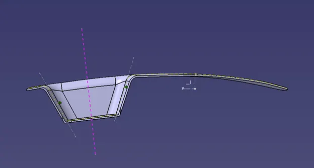
Fig 2a – PARTIAL TOOLING AXIS SKETCH
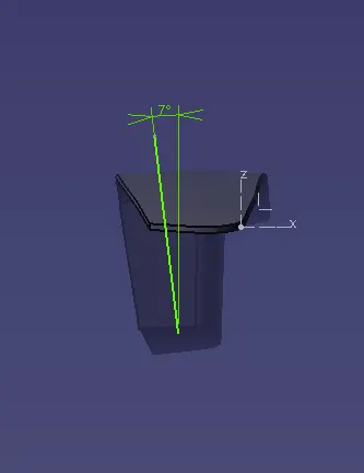
Fig 2b – PARTIAL TOOLING AXIS SKETCH
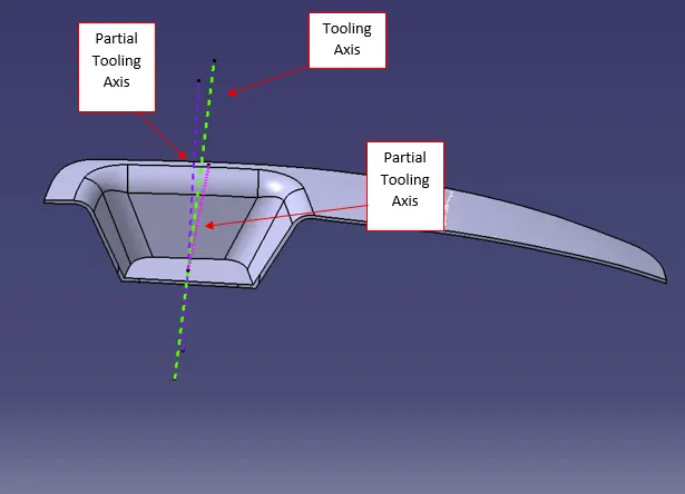
Fig 2c – TOOLING AXIS (Bisecting the Sketch Lines)
Thickened Part
After creating the Tooling Axis, we then created the Cavity and Core based on the Completed Switch Bezel Class A, B and C surfaces. We then translated the Core and Cavity to show the tooling at open position.
Feature Tree
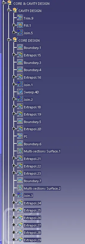
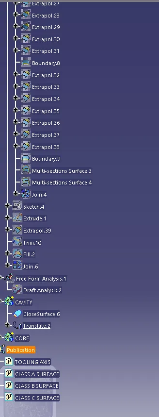
Fig 3 – Feature Tree
VIEWS
Core
Below are four views of the final Core part (Iso, Front, Side, Top):
Iso
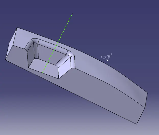
Fig 4a - Iso
Front
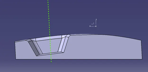
Fig 4b - Front
Side
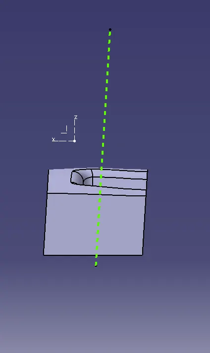
Fig 4c - Side
Top
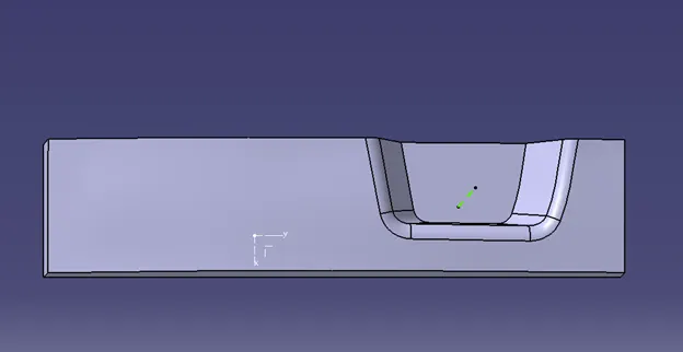
Fig 4d – Top
Cavity
Below are four views of the final Cavity part (Iso, Front, Side, Bottom):
Iso
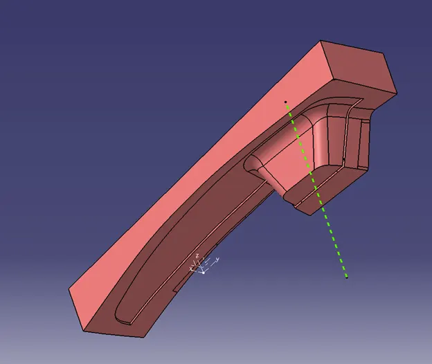
Fig 5a - Iso
Front
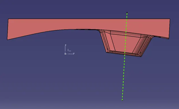
Fig 5b - Front
Side
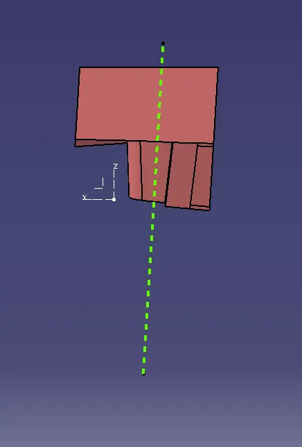
Fig 5c - Side
Bottom
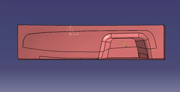
Fig 5d – Bottom
Draft Analysis
Fig 6 -- DRAFT ANALYSIS OF SWITCH BEZEL
Iso
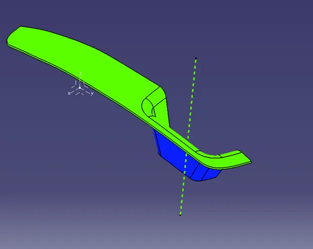
Fig 6a - Iso
Front
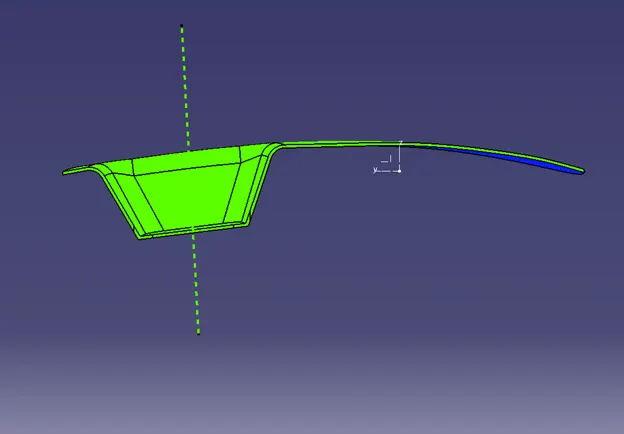
Fig 6b - Front
Side
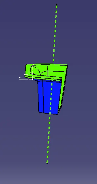
Fig 6c - Side
Top
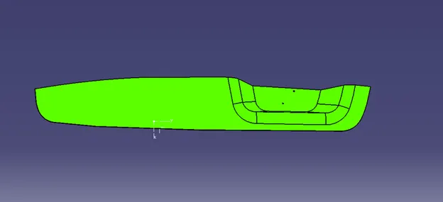
Fig 6d – Top
The Draft Analysis as shown above validated the design for manufacturability.
FINAL TOOLING
Below is the final tooling assembly with Core, Cavity and Finished Component.
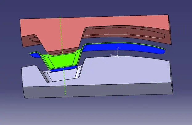
Fig 7 – Final Tooling Assembly with Core, Cavity and Finished Component
Conclusion: We were able to successfully model the Core & Cavity and verified the Switch Bezel for Draft Analysis.