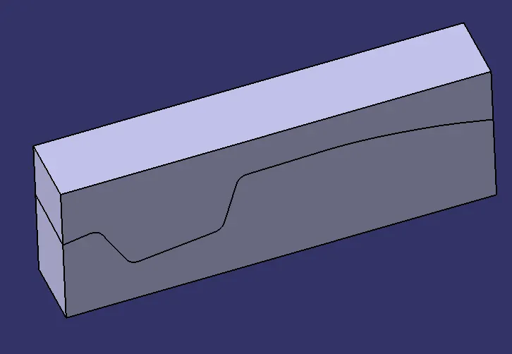
Week 8 - Challenge 6 - Core & Cavity Design
Draft Analysis:
The Draft Analysis command lets you detect if the part you drafted will be easily removed. This analysis is performed based on color ranges identifying zones on the analyzed element where the deviation from the draft direction at any point corresponds to specified values.
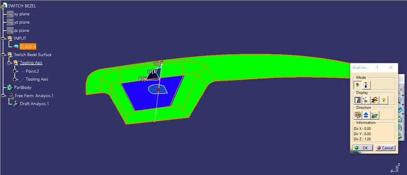
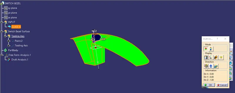
Tooling Axis creation:
Using the tooling axis created along the x and y-axis, these tooling axes are used to create the tooling axis by a bisecting method where the two lines and points will be selected as inputs.
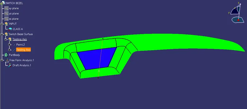
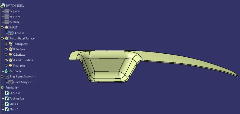
Surface:
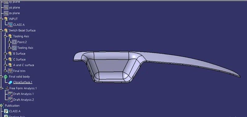
Solid part body:
Core and Cavity:
Cavity and core are used in the injection molding process, where the concave part of the mold is the cavity, and the convex part is the core. The cavity and core are used in pairs, with the cavity also referred to as the female and the core as the male.
Core Surface:
The core is the side of the tool where the plastic part is injected from, also known as the bottom half of the tool. The upper half of the mold is called CORE.
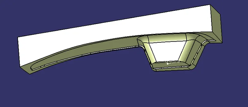
Cavity Surface:
A mold is a hollow form typically made from stainless steel with plastic injected into it to manufacture a plastic part. The plastic is inserted into the mold cavity, and a hole in the mold is shaped like the desired part.
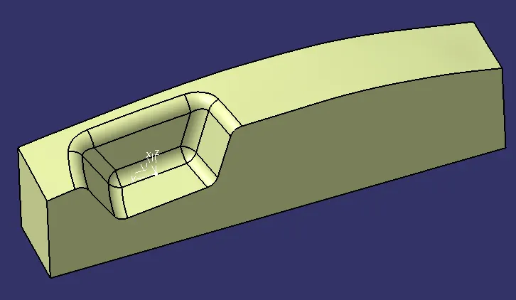
Core Solid part:
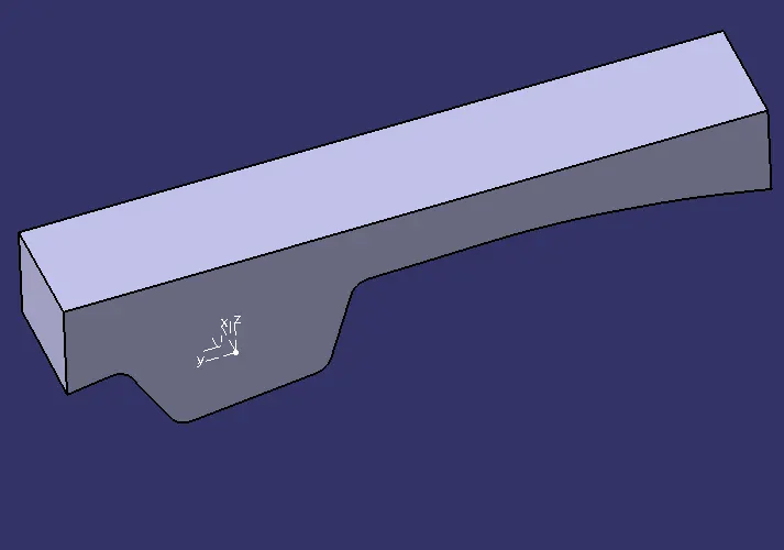
Cavity Solid part:
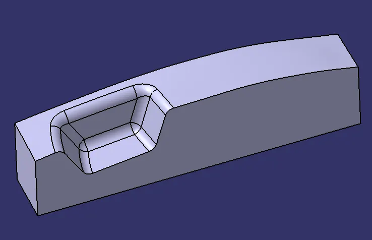
Core and Cavity block: