Wiring harness design in CATIA V5 - 3D modeling Week 4 Challenge
Objective:
To route the harness layout in the Electrical workbench using the connectors,
- DT06-4S
- DT06-6S
- DT06-2S
- DT06-08SA
Add protective covering on all branches connected to DT06-2S & DT06-4S connectors and keep the end extremity at 30mm.
Process:
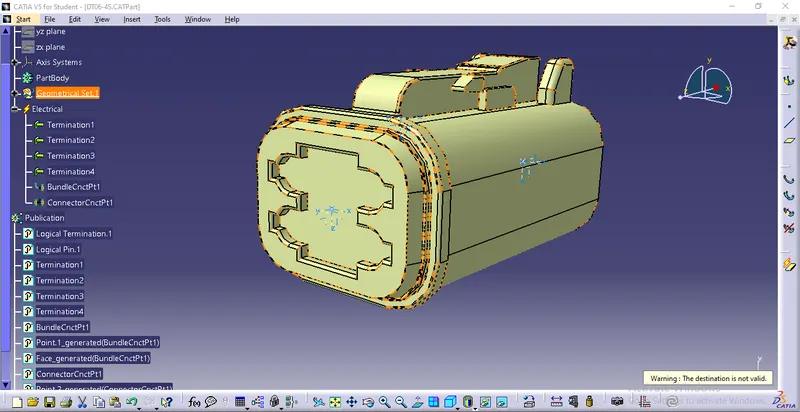
DT06-4S:
- Open the DT06-4S igs file and create a midpoint on the face using point type as between.
- Now we can create an axis system to the point we have created by using the command axis system definition.
- Make sure the x-axis is pointing towards the locking mechanism of the clip and the y-axis is pointing towards the face of the connector.
- We can create a midpoint on the entry using point type as between.
- Now we can switch to electric part design.
- Select the command bundle connection point.
- Enter the number of terminals as 4.
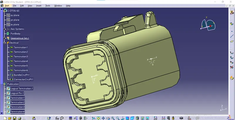
DT06-6S:
- Open the DT06-4S igs file and create a midpoint on the face using point type as between.
- Now we can create an axis system to the point we have created by using the command axis system definition.
- Make sure the x-axis is pointing towards the locking mechanism of the clip and the y-axis is pointing towards the face of the connector.
- We can create a midpoint on the entry using point type as between.
- Now we can switch to electric part design.
- Select the command bundle connection point.
- Enter the number of terminals as 6.
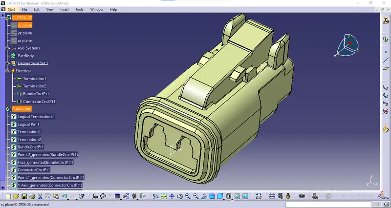
DT06-2S:
- Open the DT06-2S igs file and create a midpoint on the face using point type as between.
- Now we can create an axis system to the point we have created by using the command axis system definition.
- Make sure the x-axis is pointing towards the locking mechanism of the clip and the y-axis is pointing towards the face of the connector.
- We can create a midpoint on the entry using point type as between.
- Now we can switch to electric part design.
- Select the command bundle connection point.
- Enter the number of terminals as 2.
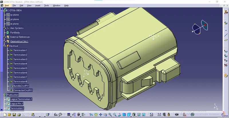
DT06-08SA:
- Open the DT06 – 08SA igs file and create a midpoint on the face using point type as between.
- Now we can create an axis system to the point we have created by using the command axis system definition.
- Make sure the x-axis is pointing towards the locking mechanism of the clip and the y-axis is pointing towards the face of the connector.
- We can create a midpoint on the entry using point type as between.
- Now we can switch to electric part design.
- Select the command bundle connection point.
- Enter the number of terminals as 8.
Harness assembly:
- Now we can open the electrical harness design workbench.
- Select the parent part and copy, and paste all the connectors we have defined.
- Now using line command in the assembly design.
- We assign the lines in the required dimensions.
- After creating the lines we can use the snap command to snap the connectors on the lines.
- Now we can select branch definition.
- We can select the branch and enter the dimensions.
- Now click on the protective covering command and set the end extremity value as 30mm.
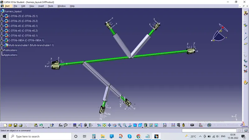
Result:
We have routed the harness layout in the Electrical workbench using the connectors,
- DT06-4S
- DT06-6S
- DT06-2S
- DT06-08SA
And added protective covering on all branches connected to DT06-2S & DT06-4S connectors and keep the end extremity at 30mm.