Wiring harness design in CATIA V5 - 3D modeling Week 5 & 6 Challenge
Objective:
To route harness layout in Electrical workbench.
Process:
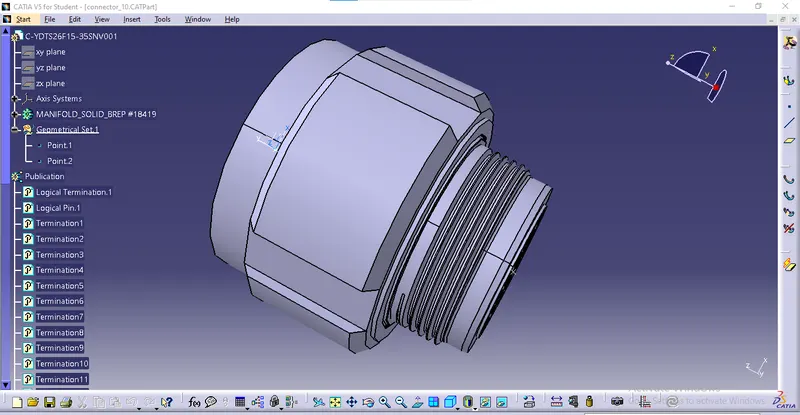
Defining the cad files:
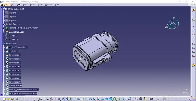
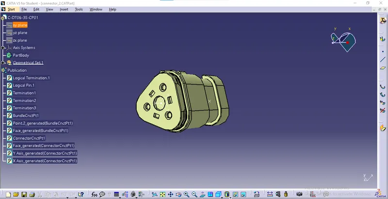
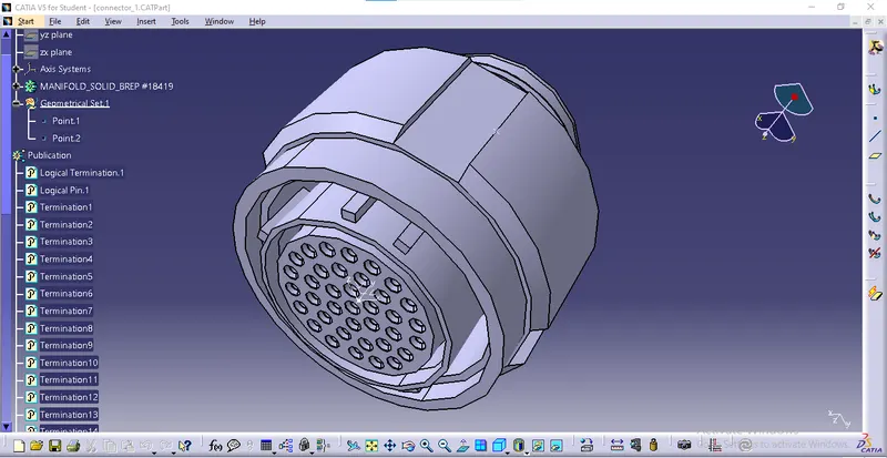
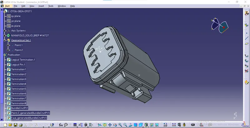
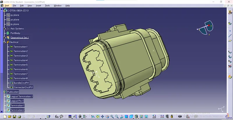
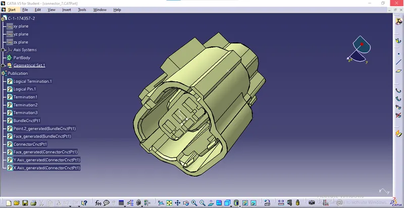
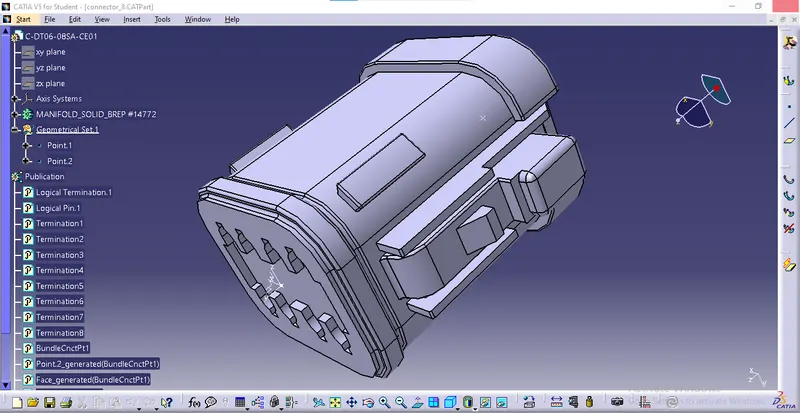
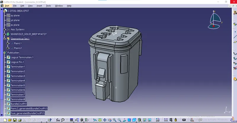
- Open the igs files and create a midpoint on the face using point type as between.
- Now we can create an axis system to the point we have created by using the command axis system definition.
- Make sure the x-axis is pointing towards the locking mechanism of the clip and the y-axis is pointing towards the face of the connector.
- We can create a midpoint on the entry using point type as between.
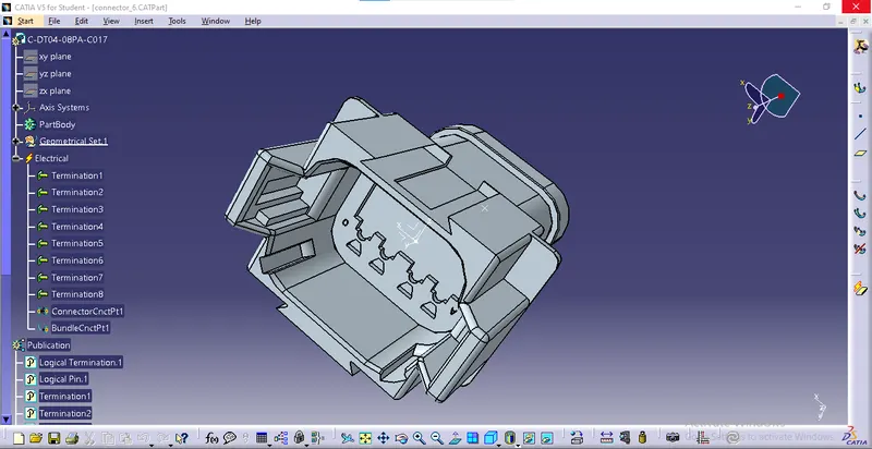
- Now we can switch to electric part design.
- Select the command bundle connection point.
- Enter the number of terminals required.
Harness A:
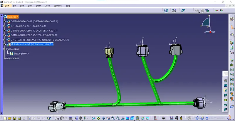
- Now we can open the electrical harness design workbench.
- Select the parent part and copy, and paste all the connectors we have defined.
- Now using line command in the assembly design.
- We assign the lines in the required dimensions.
- After creating the lines we can use the snap command to snap the connectors on the lines.
- Now we can select branch definition.
- We can select the branch and enter the dimensions.
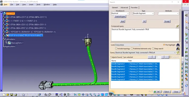
- Hold on ctrl + f the search tab will be opened.
- Now Select electrical in the workbench.
- Type as bundle segment and attribute as fully connected and select true.
- Now we can see the bundle continuity in harness A.
Harness B:
- Now we can open the electrical harness design workbench.
- Select the parent part and copy, and paste all the connectors we have defined.
- Now using line command in the assembly design.
- We assign the lines in the required dimensions.
- After creating the lines we can use the snap command to snap the connectors on the lines.
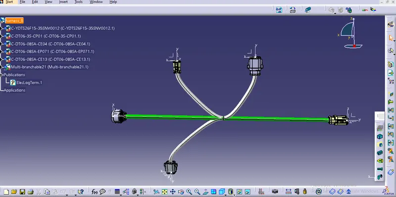
- Now we can select branch definition.
- We can select the branch and enter the dimensions.
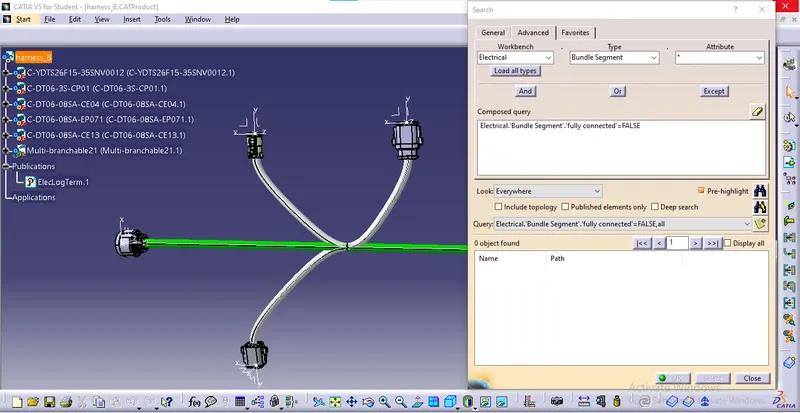
- Hold on ctrl + f the search tab will be opened.
- Now Select electrical in the workbench.
- Type as bundle segment and attribute as fully connected and select false.
- Now we can see if any bundle continuity fails in harness B.
Routing Harness:
- Now we can route Harness A and Harness B.
- open electrical harness assembly and copy, and paste Harness A and Harness B.
- Now we can open the assembly design workbench.
- Use the Manipulate command to align harness A and harness B.
- Now open the electrical assembly design workbench.
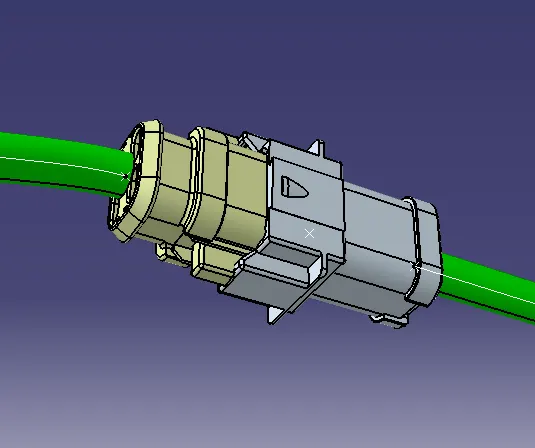
- Select connect electrical devices command.
- Now select connector 5 and connector 6.
- We can see that both the harnesses are now connected electrically.
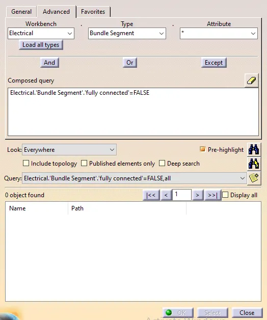
- Hold on ctrl + f the search tab will be opened.
- Now Select electrical in the workbench.
- Type as bundle segment and attribute as fully connected and select false.
- Now if any bundle continuity fails in the routed harness.
- Open the assembly design workbench and select the annotation command.
- We can name all connectors in order.
- We have named the connectors from 1 to 10.
- Now open tools and select Generate CATpart from the product.
- Now the product will be saved in igs format.
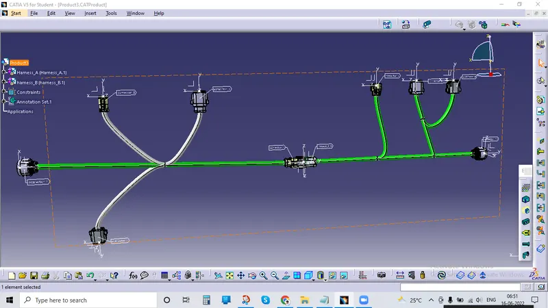
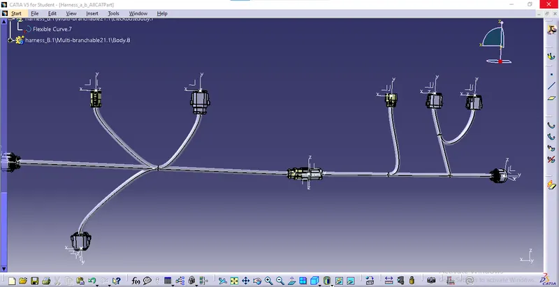
Result:
We have created two harness layouts namely harness A and harness B, using those harness layouts we have routed a harness layout in the Electrical workbench and connected them electrical without any bundle errors and bundle continuity faults. We have also created a igs format of the layout.