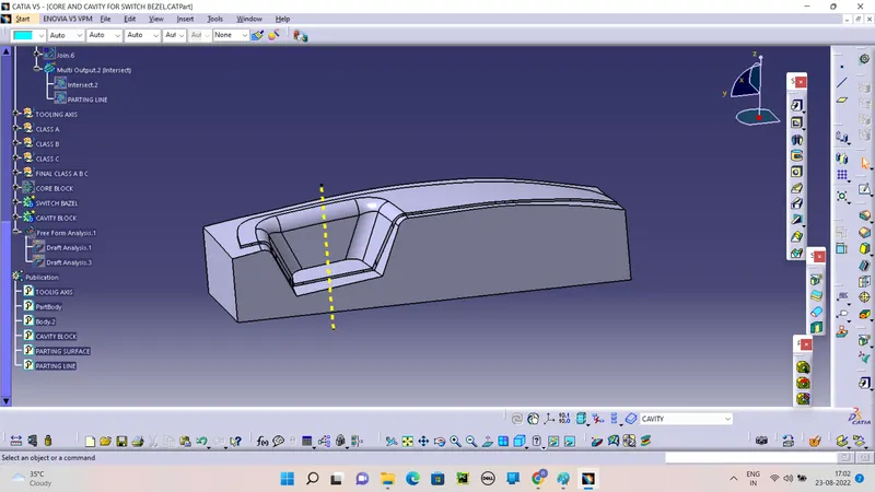
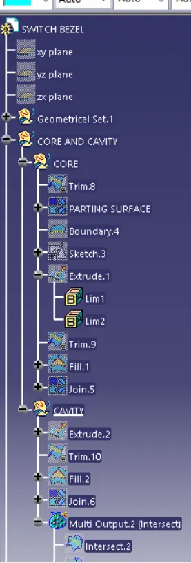
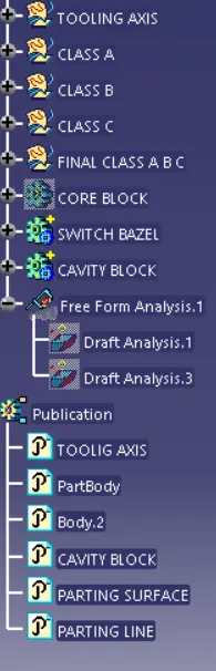
Week 8 - Challenge 6 - Core & Cavity Design
AIM:
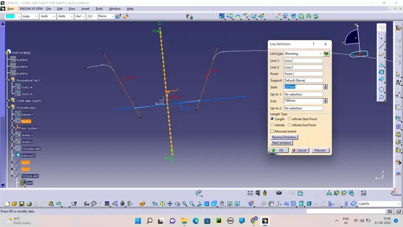
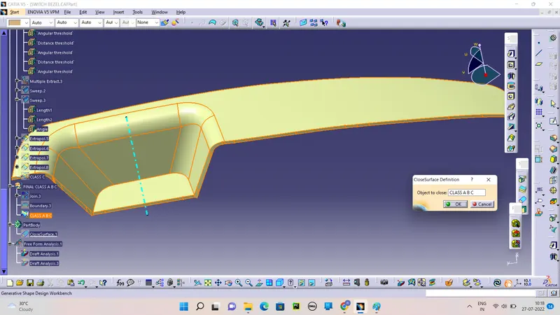
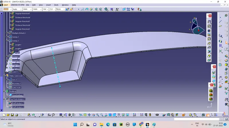
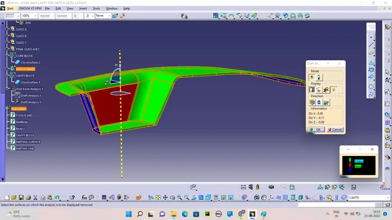
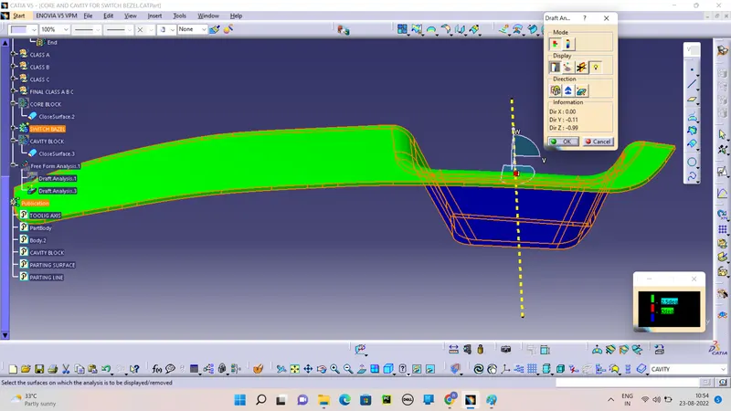
To Create the Switch Bezel Plastic component through the given Class-A surface. To begin with, the tooling axis for the given Class-A Surface should be created meeting the requirements of the draft angle and at the end perform the Draft analysis on the model.
Take the Thickness of the component to be 2.5 mm
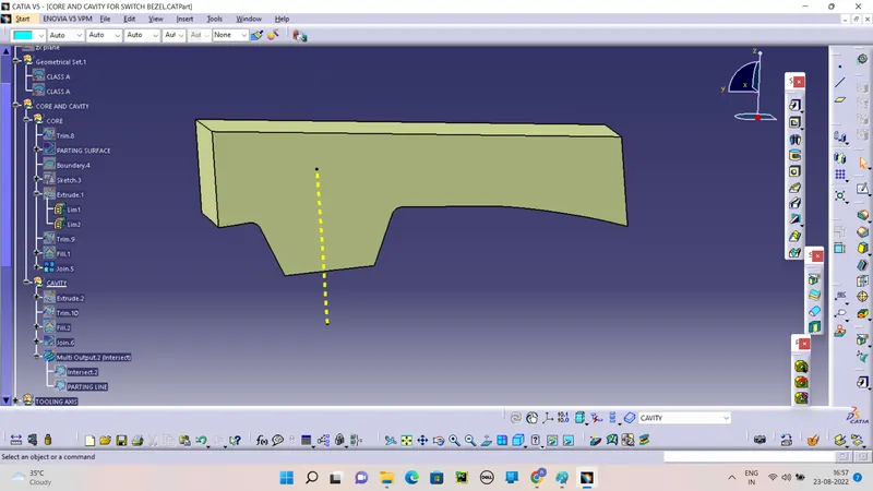
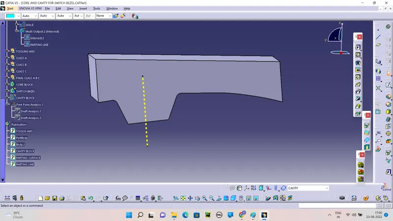
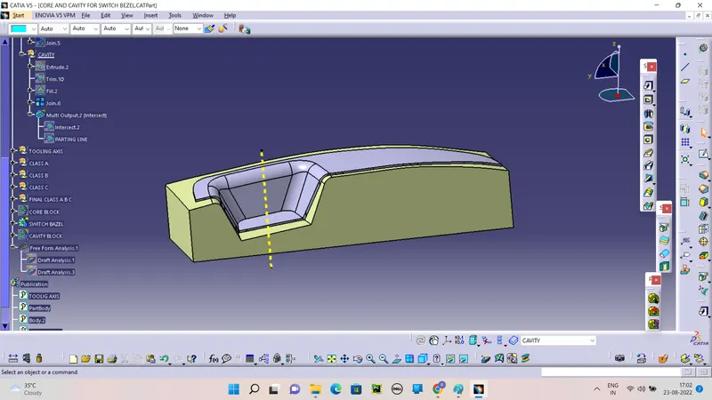
To Create the Core and Cavity for the Switch Bazel.
OBJECTIVE:
Create the parting surface and parting line.
Create Core and Cavity along the Tooling Axis.
Use the publicatio option also.
INTRODUCTION:
The control panel bezel is the frame part of the window switch that holds its switch covers and buttons into place. Moulding is the method used to manufacture the plastic trims of an automotive by most OEM’s, hence by considering the manufacturing consideration the switch bezel is designed.
With draft analysis, you can verify draft angles, examine angle changes within a face, as well as locate parting lines, injection, and ejection surfaces in parts.
Drafts are defined on molded parts to make them easier to remove from molds. There are two ways of determining the objects to draft: either by explicitly selecting the object or by selecting the neutral element, which makes the application detect the appropriate faces to use.