Week 8 - Challenge 6 - Core & Cavity Design
OBJECTIVE:
create core and cavity block for switch bezel.
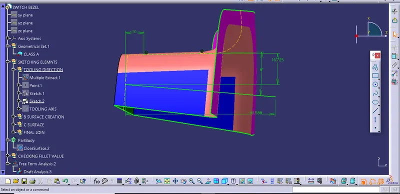
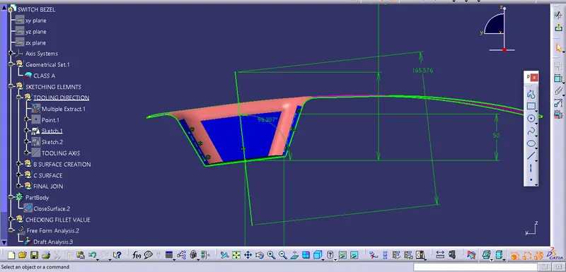
Before going into analysis, we should create tooling axis.
Procedure for Creating tooling axis:
- A reference point is created along a class a surface and using that reference point a new axis system is created.
- The X direction of the class A and Y direction of the class A were used to create tooling axis.
- Finally, the tooling axis is created by bisecting the two lines and it is published. Class A surface as input using surface operation commands class B is developed.
- The tooling axis determines the direction of class C boundary swept with draft direction.
- When viewing from tooling direction normal all the parts that are drafted should be visible so it gives an rough idea to determine product manufacturing in injection molding.
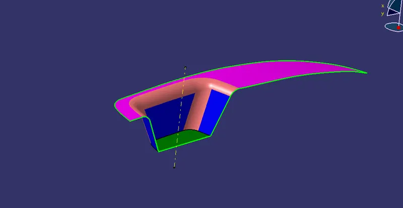
CORE AND CAVITY DESIGN :
So before designing the core and cavity we have to create parting surface.
arting Surface:
At first we have to create parting surface,
- Creating parting surface, we need to use class A class B class C surfaces.
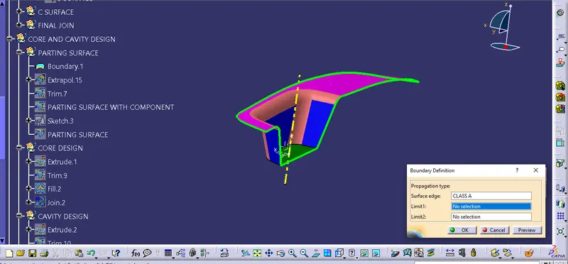
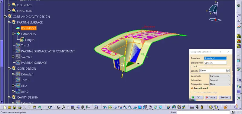
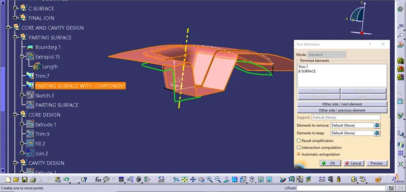
- Using Boundary command create a boundary around the switch bezel component, and now extrapolate the edges of class A.
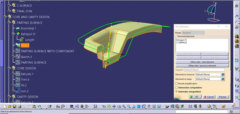
- Now Trim the extrapolated surface with Class C surface to form new trimmed component, and also trim with the class B surface.
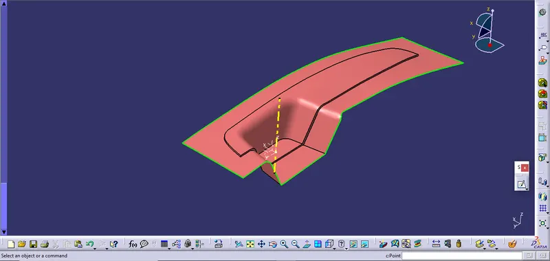
- The parting surface is formed. Make sure that the parting surface should be always be at B surface.
Core Design:
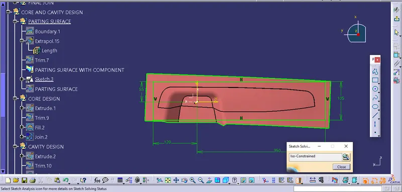
- So now create a sketch in XY plane, make sure that the sketch should be inside the parting surface.
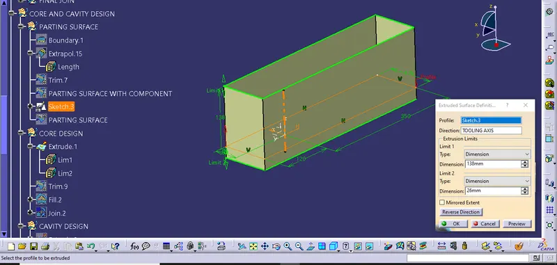
- Now Extrude the sketch using tooling axis as direction. So, extrude is formed in the direction of tooling axis
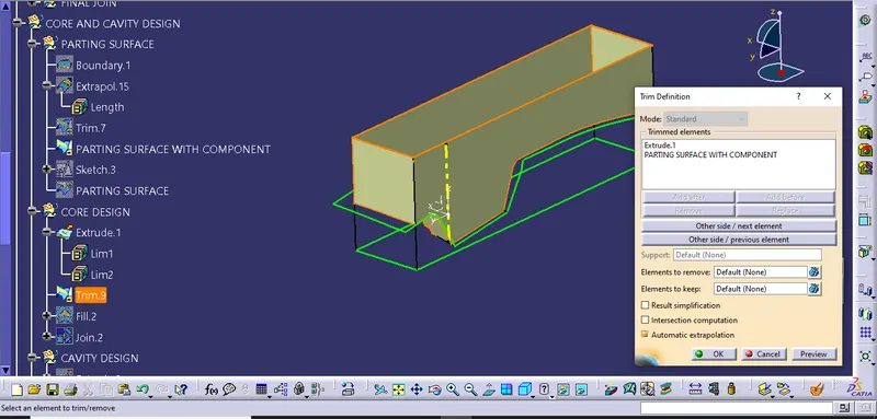
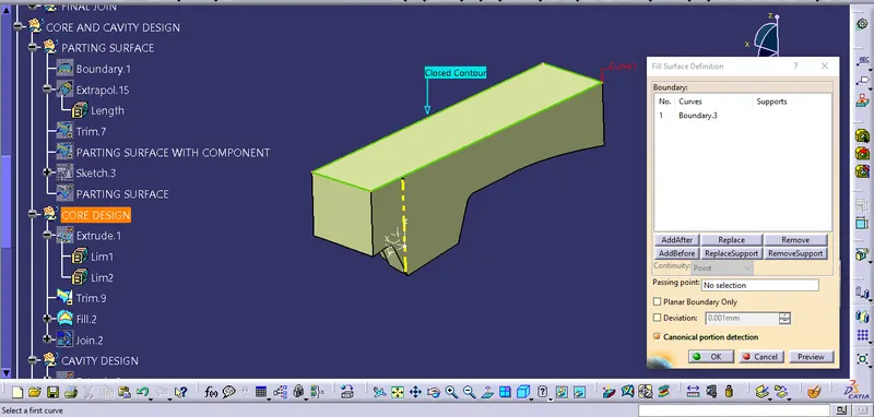
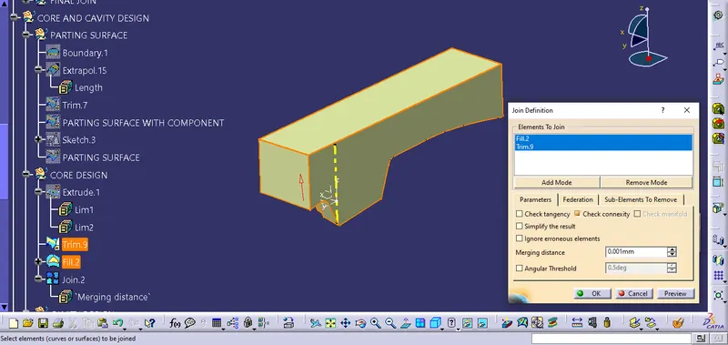
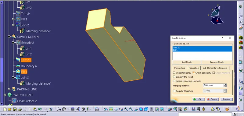
- So now trim the extruded surface with created parting surface. Now fill the surface using fill command so a closed surface is formed. So join all surfaces to make sure there is no gap between the surfaces,
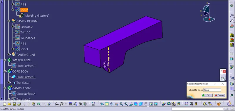
- Now convert the closed hollow surface into the closed body. so the core body is formed.
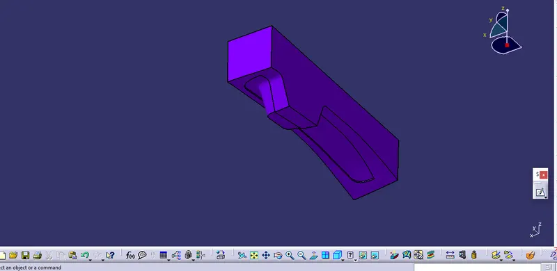
Cavity Design:
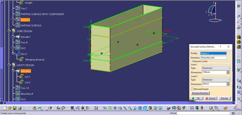
- Now again extrude the sketch created in XY plane, using direction as tooling axis direction.
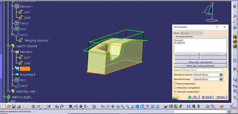
- Now trim the extruded surface with B surface.
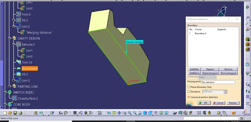
- Now fill the close surface using fill command.
- And join the surfaces using join command make sure that there is no gap in between them.
- Now convert the closed hollow surface into the closed solid body
- And the cavity body is formed.
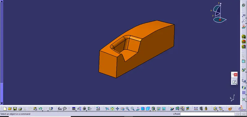
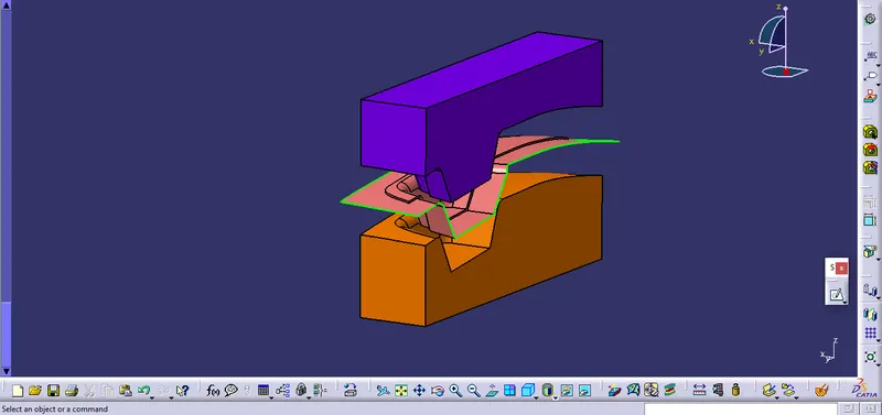
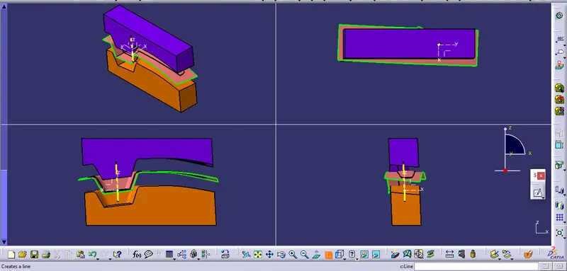
FINAL CORE AND CAVITY BODY
Procedure for Draft analysis:
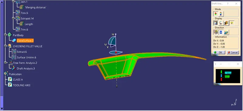
- The part created has to be changed to material in display frame.
- Then by enabling compass definition the axis system is pan along the direction of the part and aligned in line with the tooling direction.
- Lock direction is applied that fixes the compass and then the mode dialog box is formed by snapping at any point on the part.
- The color codes are classified, and draft angle are applied.
- Then the running point analysis is used to hover around the part to analyze the permissible draft angles and the analysis is saved.
VIEWS:
ISOMETRIC VIEW, TOP VIEW, FRONT VIEW, SIDE VIEW
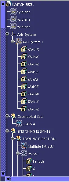
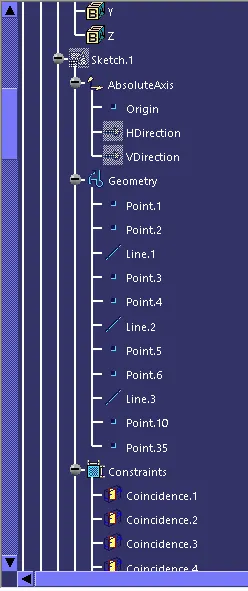
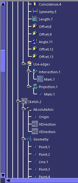
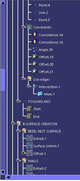
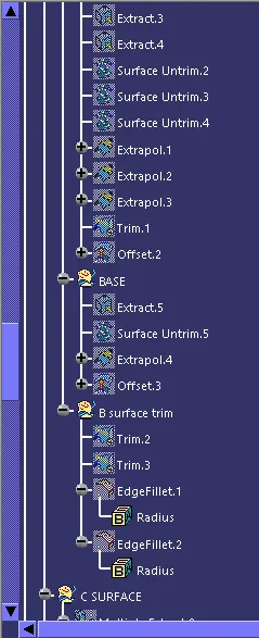
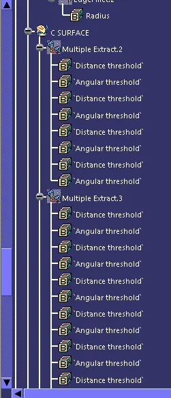
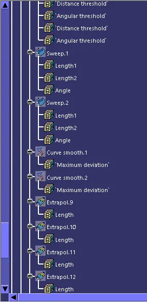
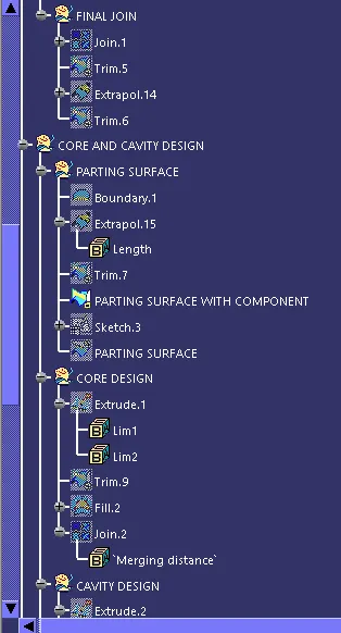
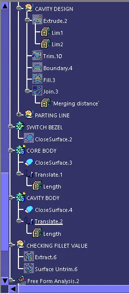
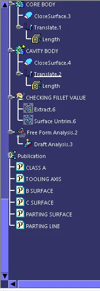
FEATURE TREE