Week 8 - Challenge 1 - Draft Analysis on a Fan Cover
DRAFT ANALYIS
OBJECTIVE:
Creating the tooling axis for the given Fan cover model meeting the requirements of the draft angle and perform the Draft analysis on the model.
ANALYSIS APPROACH:
- Before going to analysis we need to check the continuity of the given class A surface. There should be no discontinuity in between the surfaces of a component.
Checking the continuity of given class A surface
- There are two possible ways to check the continuity of the surface
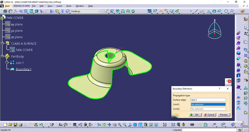
- JOIN COMMAND
- BOUNDARY COMMAND
JOIN COMMAND:
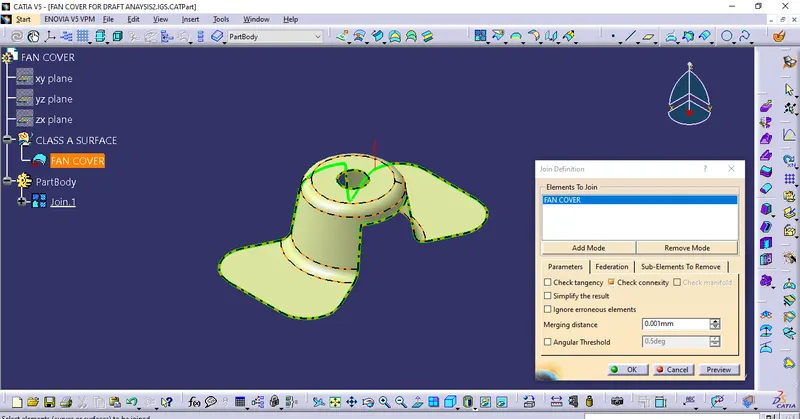
- Below image shows that the surface has no discontinuity, the green colour boundary indicates the continuous connected boundary.
BOUNDARY COMMAND:
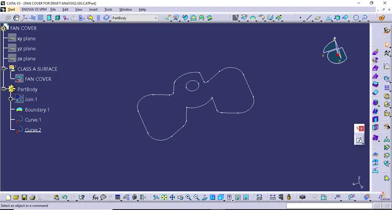
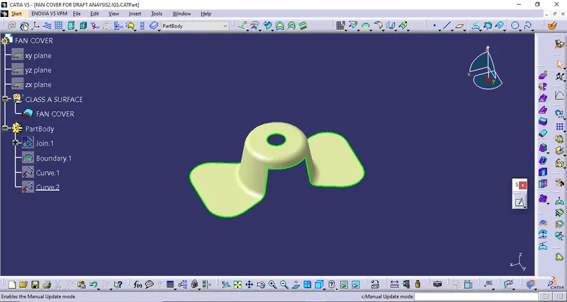
- Extracting the boundary of a given class A surface we also check the continuity of the surface visually, below two images shows the continuity of the component.
Defining Tooling axis:
Next is to define tooling axis of the component. Tooling axis is a direction in which mold or core & cavity opens. Analyzing the model to see which direction is most suitable for tooling axis. From below image it can see that surface has hole at its top and cutouts at sides.
- From X DIRECTION as tooling axis as shown below image we require side core for top hole which increases mould cost.
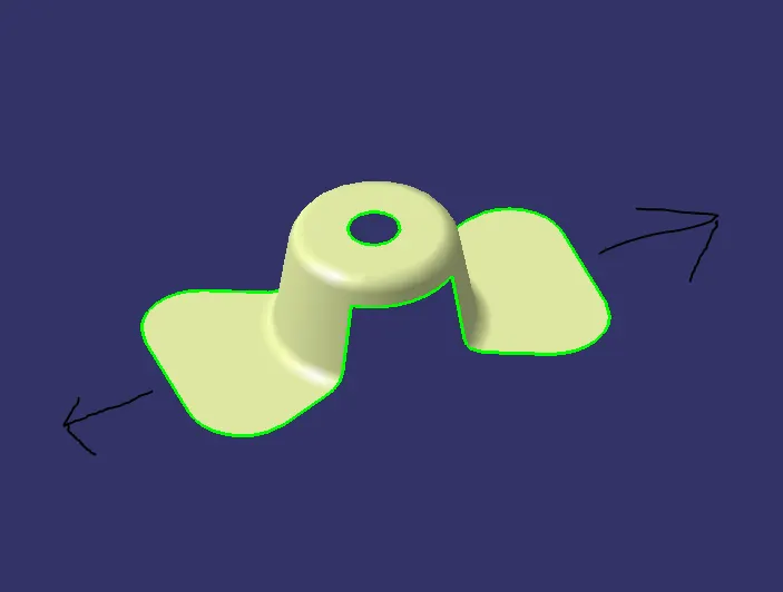
- From Y DIRECTION as tooling axis as shown below image we require side core for top hole which is also not require.
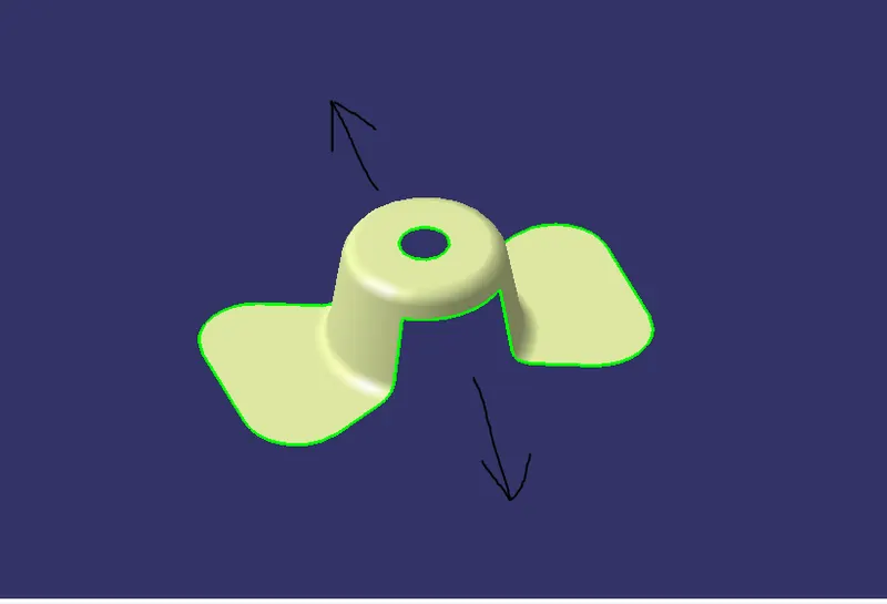
- So Z DIRECTION as tooling axis we clear this hole in tooling and this is dummy tooling axis.
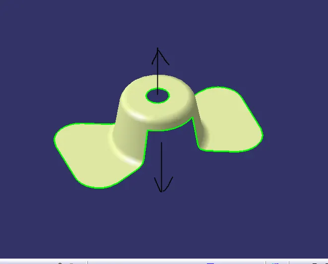
Now we will use bisecting method to find real tooling axis
- Insert axis system take intersection of ZX plane with class A surface we will get the two curves.
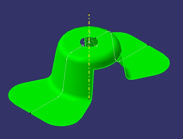
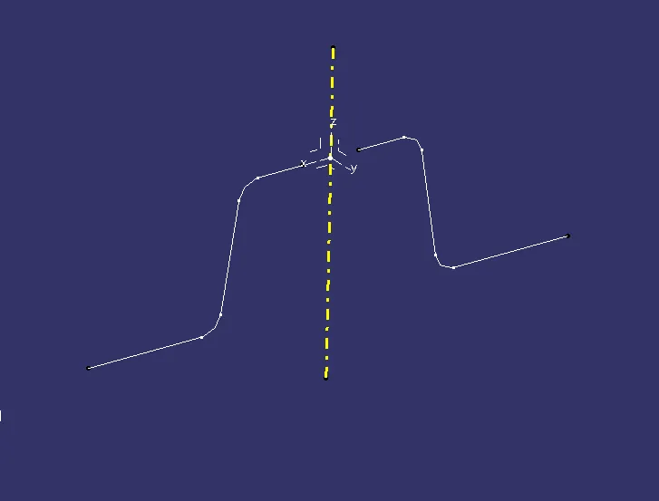
- Now we have to see which surface will create problem or will be difficult for tooling. Because the surface which 900 to tooling axis will be cleared. So we have to check surface which lie parallel to tooling axis direction. Make line along parallel surface using point to pint direction. Here we get two lines now we will bisect the two lines and choose vertical direction. This will be our tooling axis for x direction.
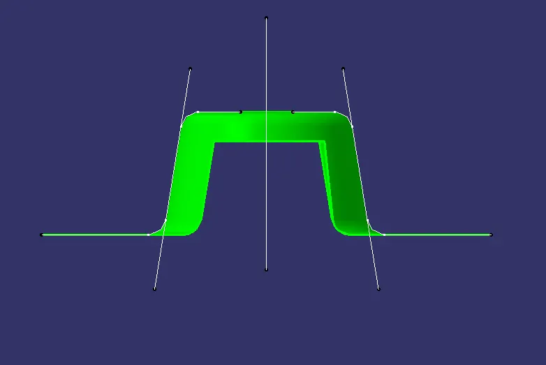
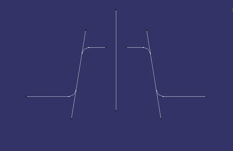
- Similarly we intersect yz plane of the axis system with the class A surface and repeat the same procedure again.
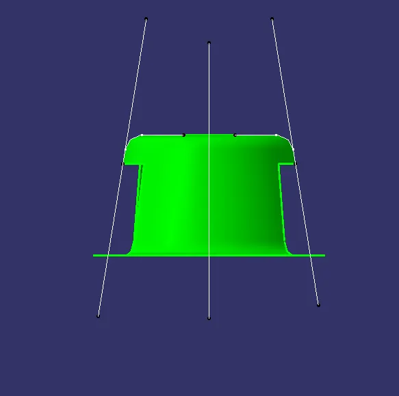
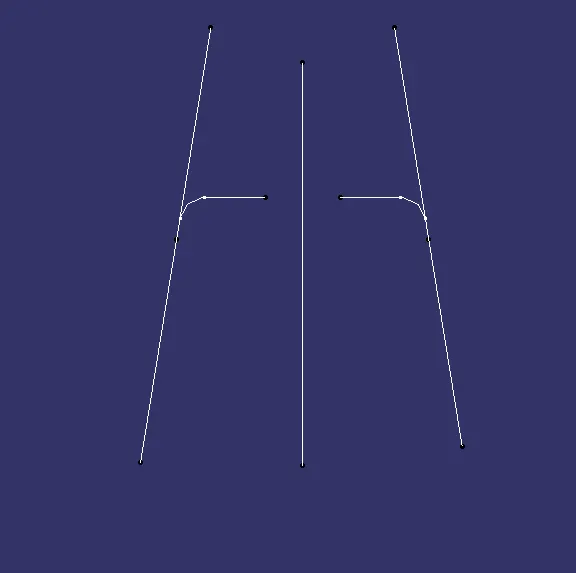
- Now we have two axis i.e. tooling clearing x axis and tooling clearing y axis. We will bisect these two axis to get our final tooling axis.
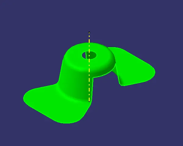
Draft analysis:
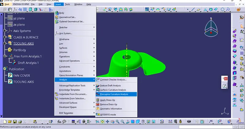
- To perform draft analysis, Go to insert - Analysis - Feature draft analysis.
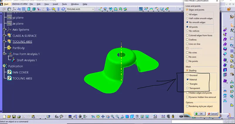
- Before that switch customize view parameter mode to material.
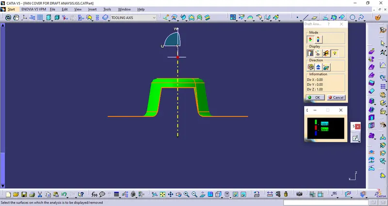
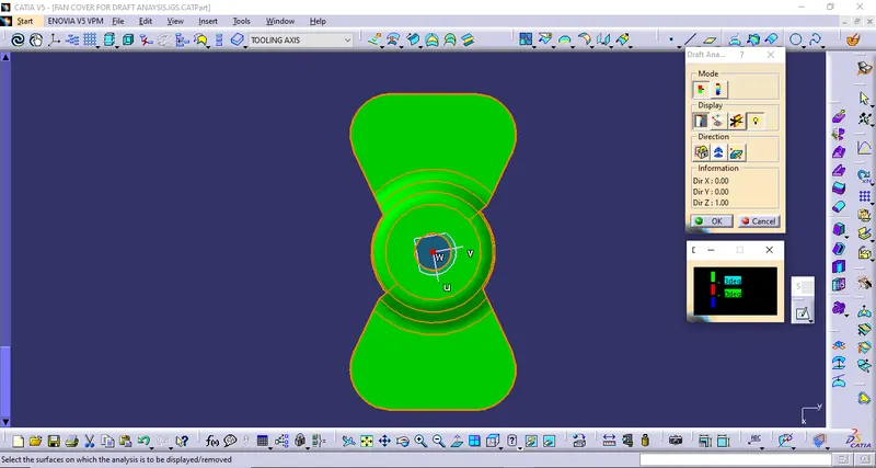
- Click on compass icon and align it with the tooling axis and click on the surface, we will get our results.
So below images are drafting results of a Class A surface of Fan cover
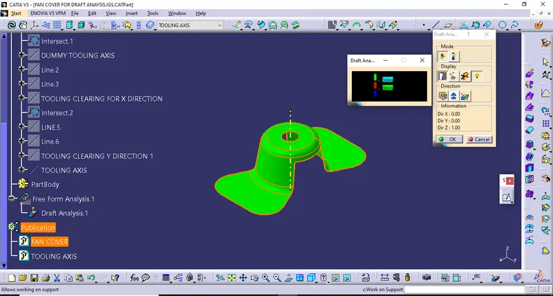
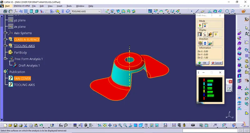
- Below images shows the Analysis under the running point.
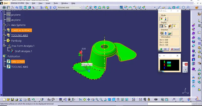
VIEWS
Isometric view
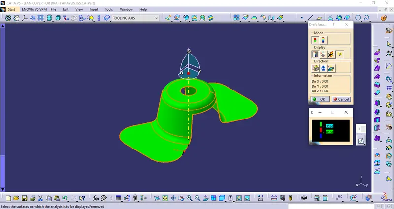
Front view
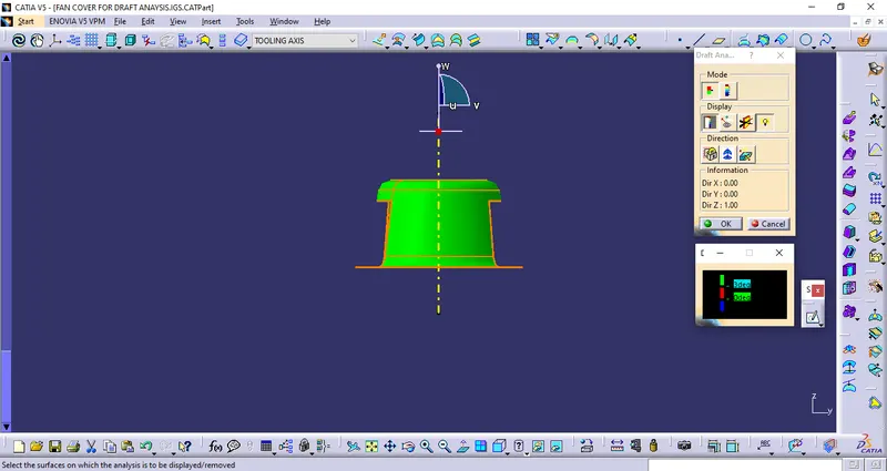
Side view
Top view
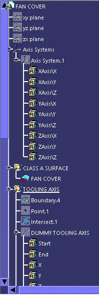
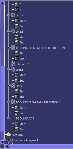
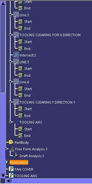
Feature tree