Week 8 - Challenge 6 - Core & Cavity Design
Create the Core and cavity blocks for the switch bezel designed in the earlier challenge.
AIM:
To create a switch bezel from the given A-class surface by considering a thickness of 2.5 mm and also creating Core and Cavity blocks for it.
class A surface :
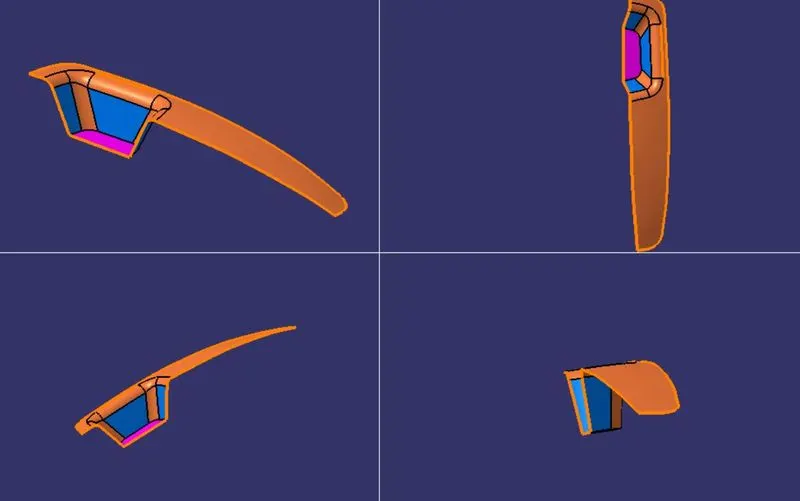
The input of the product designer is in the form of the A-class surface. The job of the product designer is to create the B and C surfaces keeping all the aspects of the mold.
Class A surface comes without rib, emboss, or screw hole. Class A surface is made from scanned data with different software like alias class b and c have some feature.
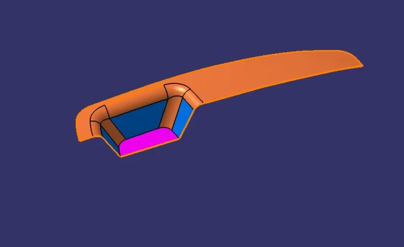
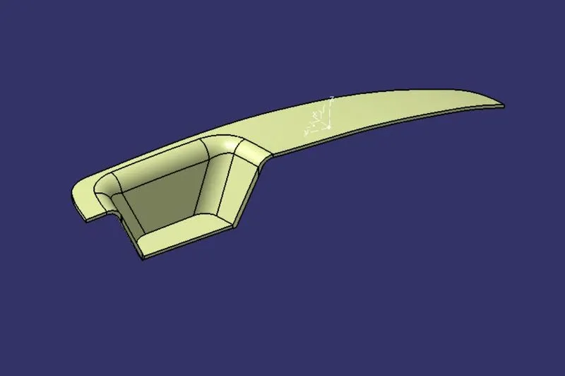
CLASS A SURFACE IS SHOWN AT A DIFFERENT ANGLE
Tooling Axis:
IT IS THE AXIS IN WHICH THE DIRECTION CORE AND CAVITY OPEN. THIS IS THE VERY IMPORTANT FOR THE PRODUCTION OF PLASTIC COMPONENTS. MOST OF THE DEFECTS WILL BE DONE IMPROPER TOOLING AXIS CREATION BY THE PLASTI DESIGNER.
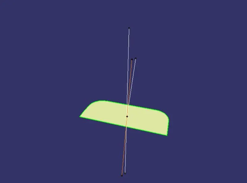
The tooling axis is created with help of a base plate two lines is drawn and the bisecting line is our tooling direction.
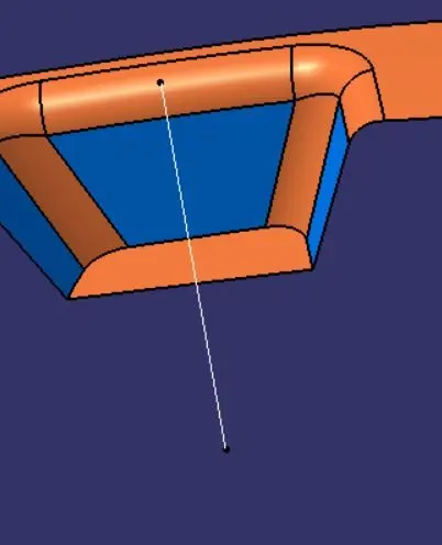
Creation of Class B:
- Now for Class B creation, we have extracted surfaces from Class A and untrimmed them to obtain the original parent surface.
- These surfaces are then offset to the required thickness.
- After offsetting, all the surfaces are trimmed into the required shape.
- Required fillets are given to the surfaces.
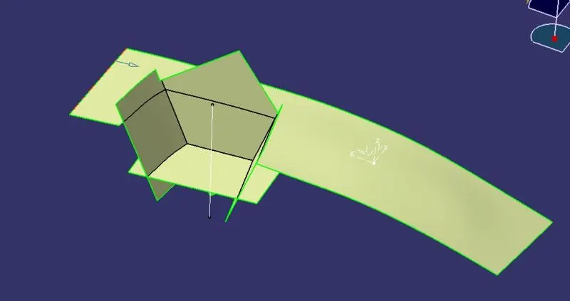
THE BOTTOM PLATE, SIDE WALL, AND TOP PLATE ARE SHOWN AND TRIMMED TO GATHER.
C class surface :
Class C Surface has swept along the boundary CLASS A surface with respect to the tooling axis direction with a draft angle of a maximum 3 degrees minimum of 0.5 degrees.
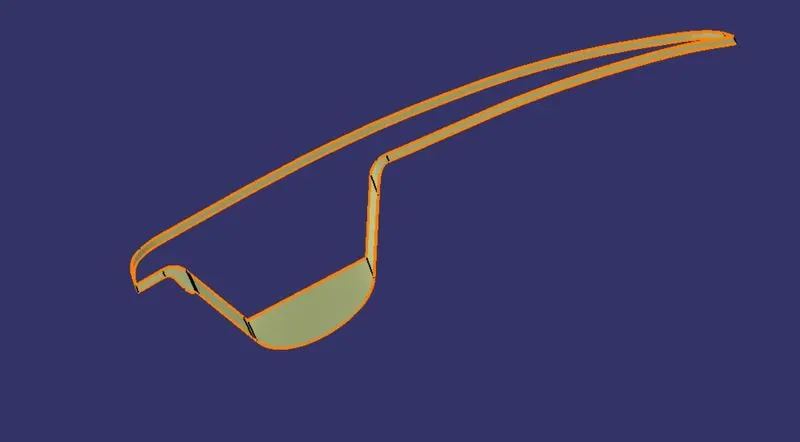
number of sweep command is used to create this class c surface
class c was created with the help of a sweep
and show bellow
also, encure that class c should be pass 3 degrees of draft angle
complete A, B, AND C are shown in the join
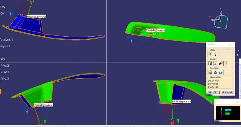
Draft analysis :
The Draft Analysis allows the user to easily analyze a part for a proper draft angle. A Draft Angle describes the amount of taper for molded or cast parts perpendicular to the parting line. Find the Draft Analysis in the Tools tab. Draft Analysis is applicable for 3D part models.
The draft analysis button within CATIA V5 will help you quickly gather the draft angle on multiple surfaces without the need for tedious manual measurements. Here is a quick rundown of how the icon works when you have a given die direction.
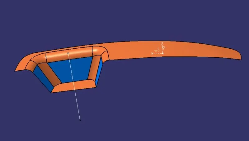
For the purpose of this demo, I have a part with several drafted surfaces that is oriented in vehicle location (i.e. not perfectly aligned with x, y, or z direction)
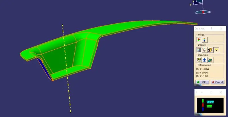
DRAFT ANGLE IS SHOWN AT A DIFFERENT ANGLE
CORE AND CAVITY design for switch bezel:
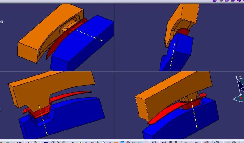
CORE AND CAVITY
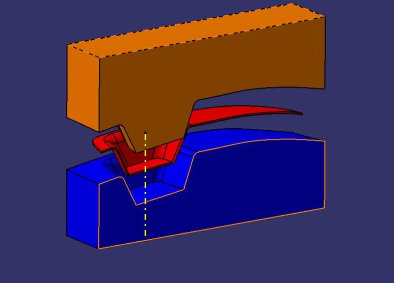
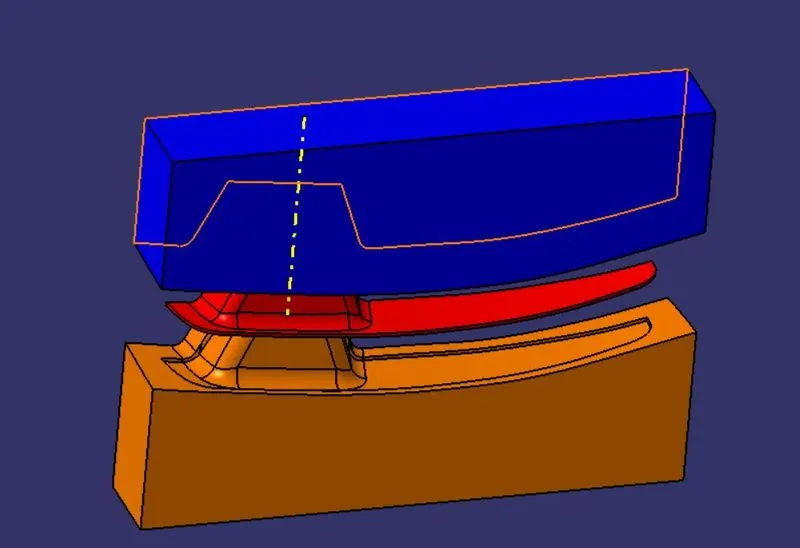
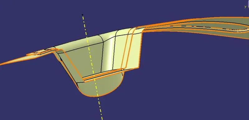
a core is the one part of the mold. and it is responsible for half of the molded part. actually core is the projection of the body and the cavity is the depression of the body. these core and cavity combine to form a mold. then the plastic material is injected into this mold to get a plastic part.
CREATION OF CORE IS SHOWN BILLOW
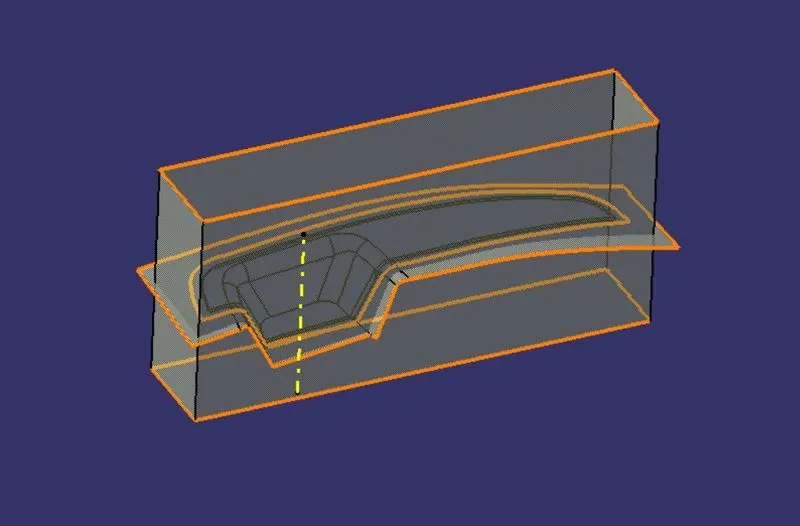
CORE FINAL TRIM
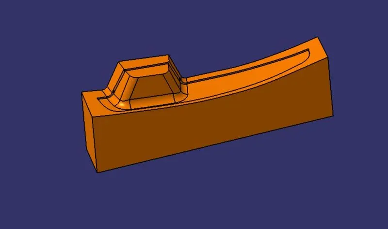
CAVITY DESIGN
- The cavity is the part where the injector and filling of the molten plastic happens. The cavity block is prepared by first extruding the outer boundary along the tooling direction.
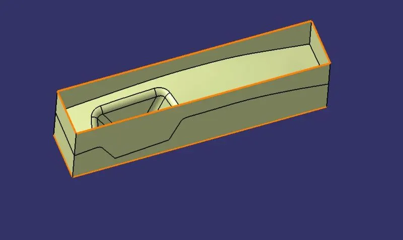
FINAL CAVITY
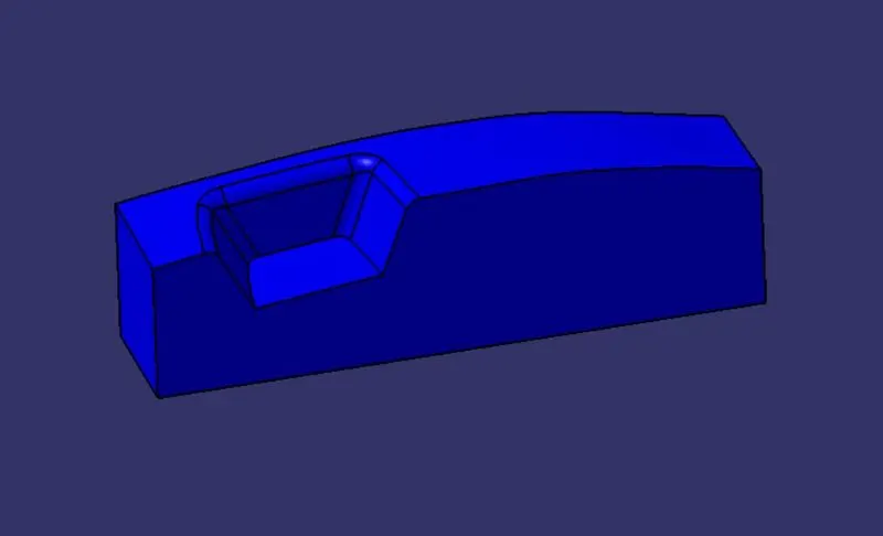
THE INTERSECTION IMAGE IS SHOW BELOW FOR CLEAR UNDERSTANDING
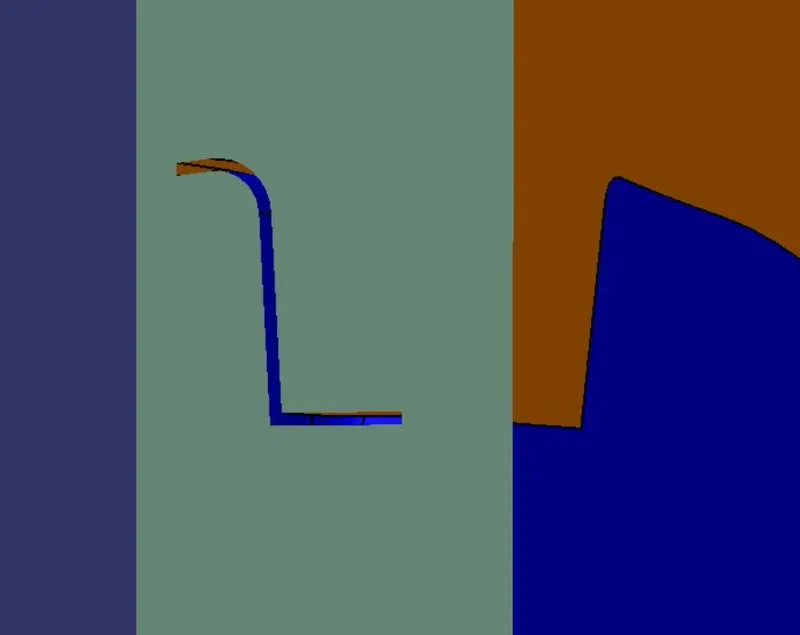
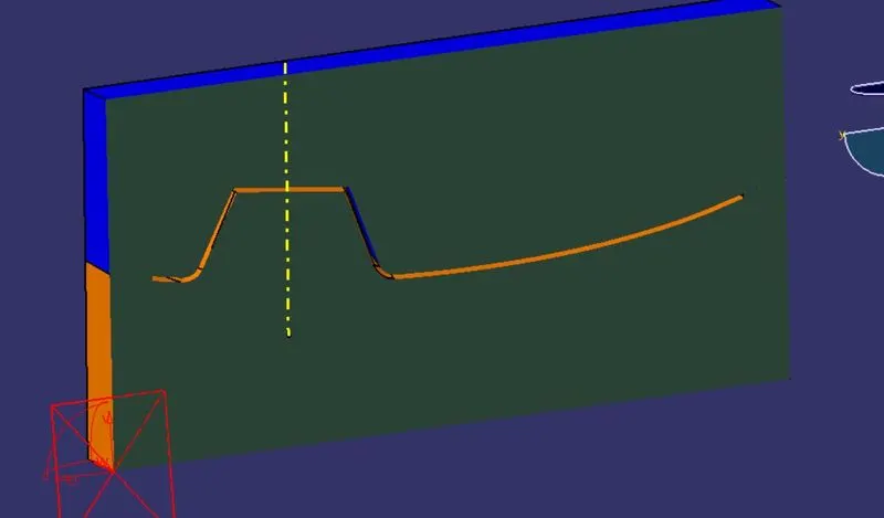
THE INTERSECTION LINE SHOWS THAT PARTING LINE AND CORE AND CAVITY
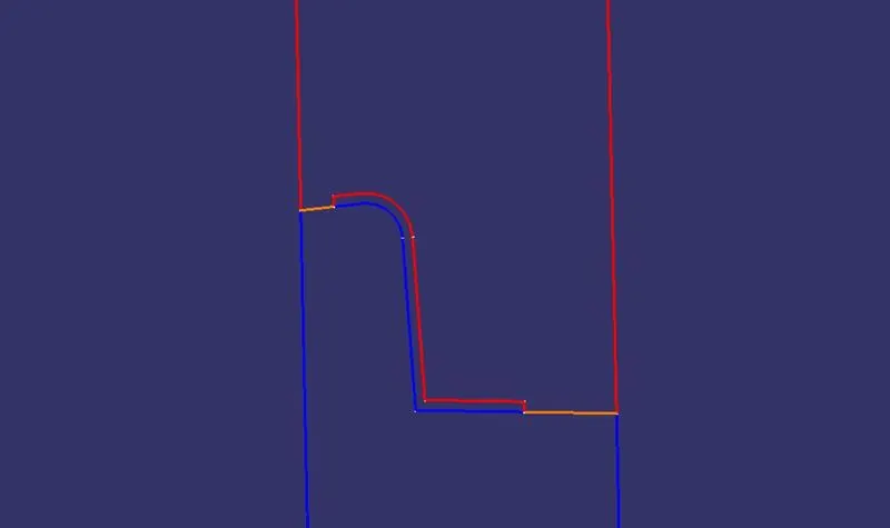
BLUE LINE SHOWS THAT CAVITY
RED LINE SHOWS THE CORE AND
ORANGE LINE SHOWS PARTING SURFACE
Tree Structure
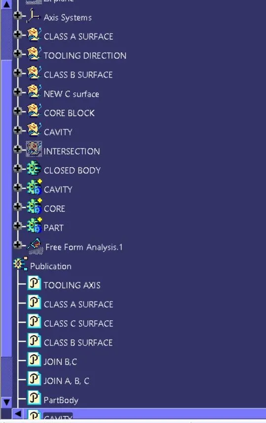
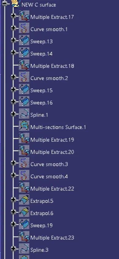
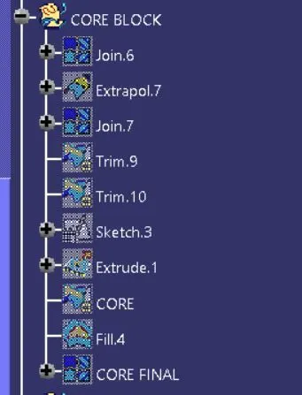
SOLID BODY TREE Structure is shown bellow
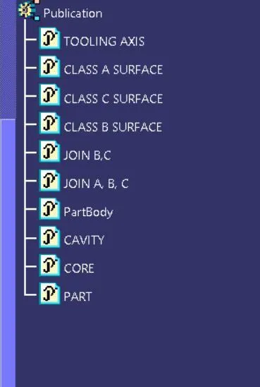
publication tree image is shown bellow
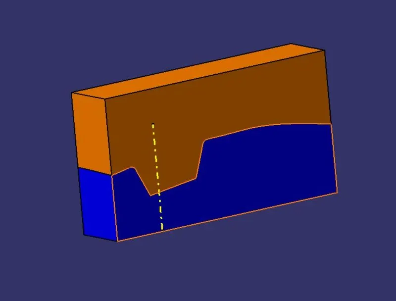
CORE AND CAVITY BLOCK IS SHOWN TO GEATHER