Week 8 - Challenge 6 - Core & Cavity Design
CORE AND CAVITY DESIGN
AIM:
To create the core and cavity blocks for the switch Bezel component.
Software used:
Catia V5
Given Class A
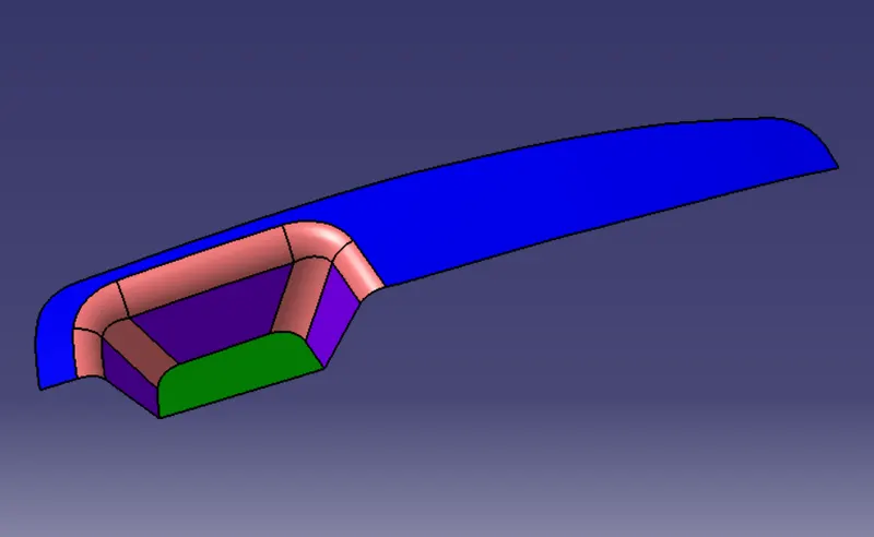
Creation Of Tooling Axis
To continue the designing process we need create the tooling axis first for the surface.
The tooling direction is created by bisecting method.
- The base surface of the class-A was extracted and a point is made at the center and an axis system is inserted.
- Then using project intersection along yz plane is created and the two inclined lines were drawn inside the positioned sketch.
- Then the bisecting lines with the two inclined lines were drawn.
Now the same is done along the xz plane but on one side we don't have inclined lines so the center point is used to extrude a line along the z-direction.
With the two lines from sketches 1 and 2,the bisecting line is created and published as tooling axis.
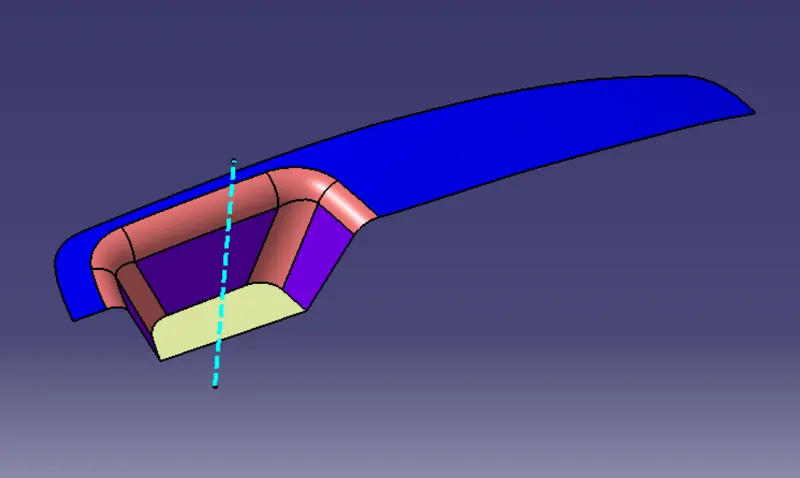
And also the class B and class C are created accordingly.
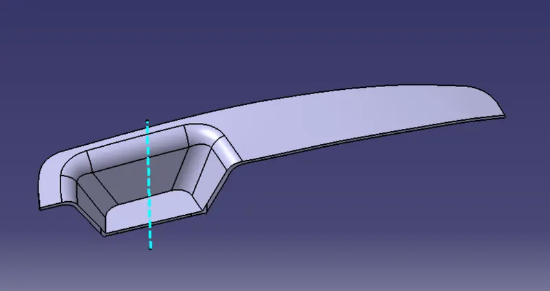
Final solid:
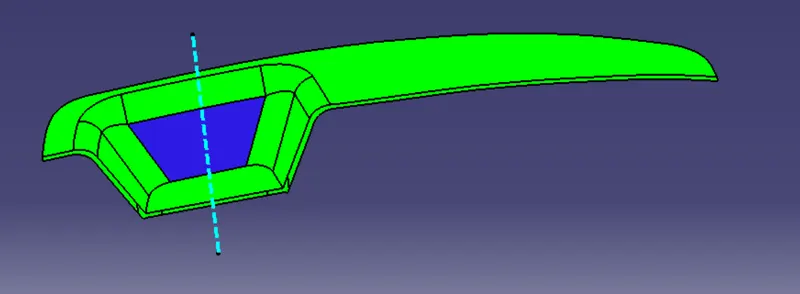
After Draft analysis:
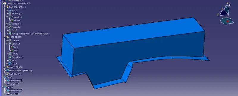
CORE DESIGN
- Core is a portion of the mold that goes inside a cavity to form the interior of a hollow part.
- Core-cavity is a term used to describe a mold created by mating A-side and B-side mold halves.
 c
c
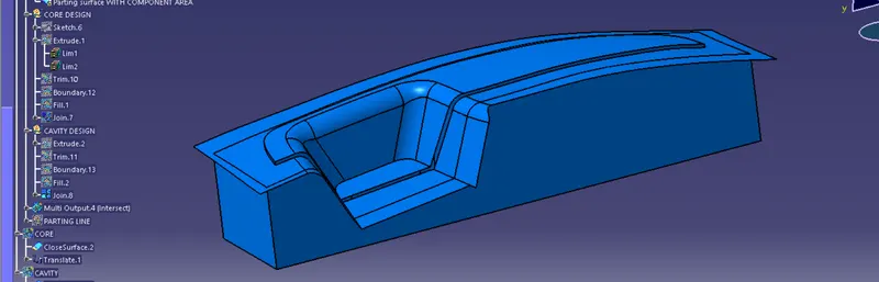
CAVITY DESIGN
- A mold is a hollow form typically made from stainless steel that has plastic injected into it to manufacture a plastic part.
- The plastic is inserted into the mold cavity, which is a hole in the mold shaped like the desired part.
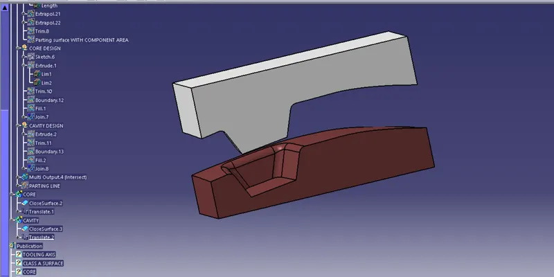
CLOSED CORE AND CAVITY PART:
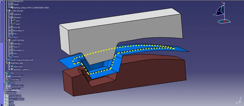
CORE AND CAVITY WITH PARTING LINE AND PARTING SURFACE
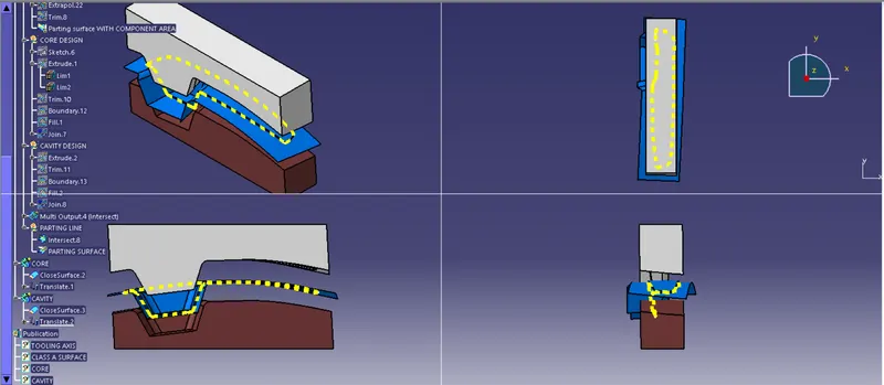
CONCLUSION:
THE CORE AND CAVITY BLOCKS FOR SWITCH BEZEL IS DESIGNED.
*********************************************************************************************************************************************************