Week 8 - Challenge 5 - Door Trim Lower
DOOR TRIM LOWER DESIGN
CLASS A SURFACE
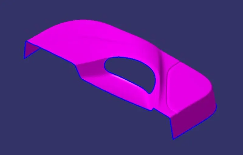
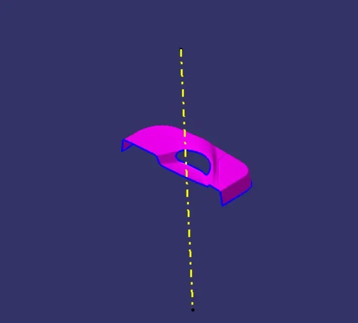
TOOLING AXIS
Tooling direction is the main consideration for plastic part and mould parts because it defines the movement of the mould part and the possibility of the plastic part coming out from the mould part (Core and Cavity).
TOOLING DIRECTION
- In Molding, machine arrangement is given to open the mould along a direction which is known as Tooling Direction.
- In other words. The mould is built from two separate halves (Core and Cavity) and tooling direction basically defines the direction of mould pulls apart.
- Tooling direction is known as primary direction.
DRAFT ANALYSIS FOR CLASS A SURFACE

CLASS B SURFACE
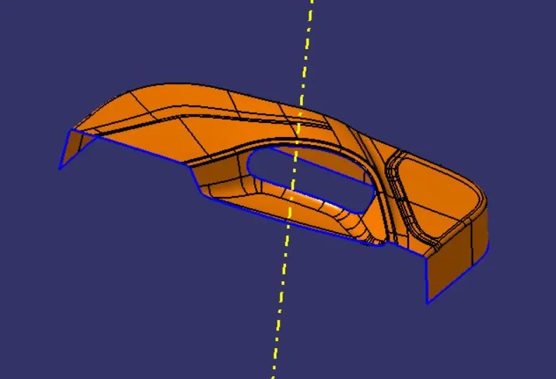
INNER C SURFACE
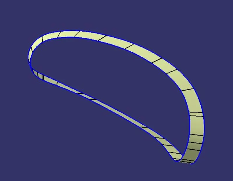
OUTER C SURFACE
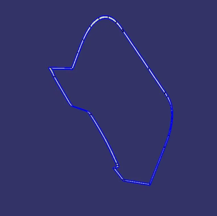
CLASS A CLASS C JOIN
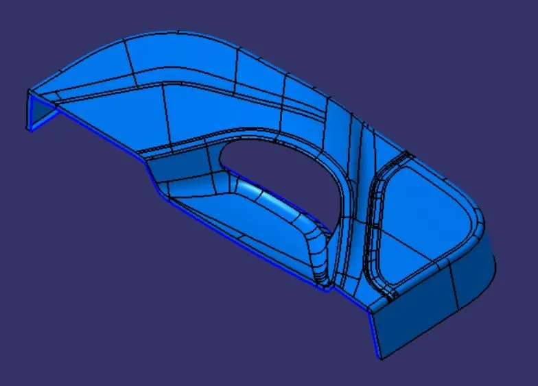
FINAL COMPONENT
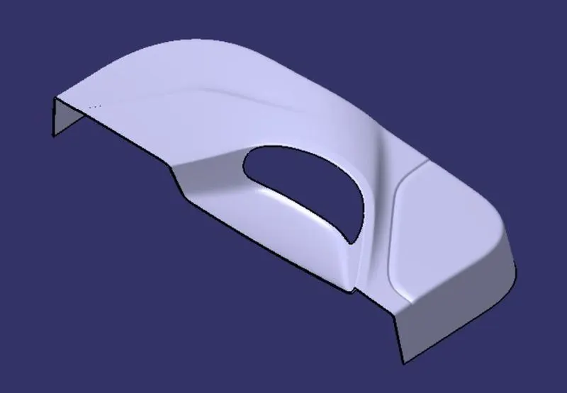
TREE STRUCTURE
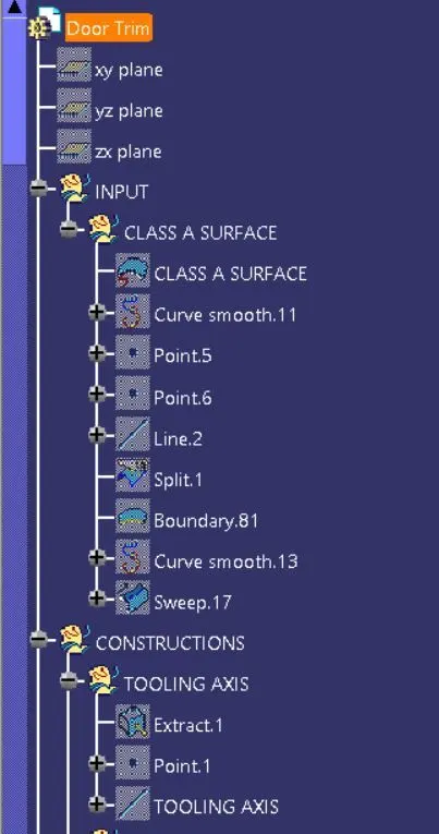
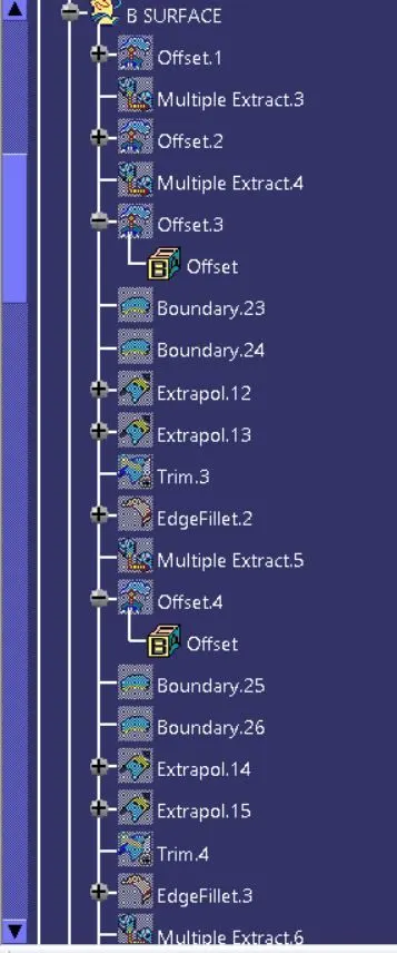
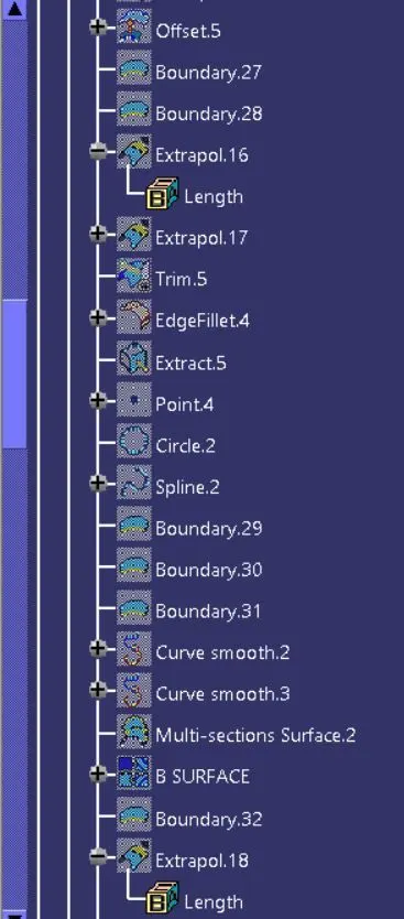
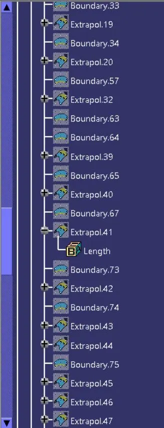
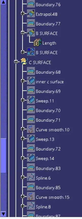
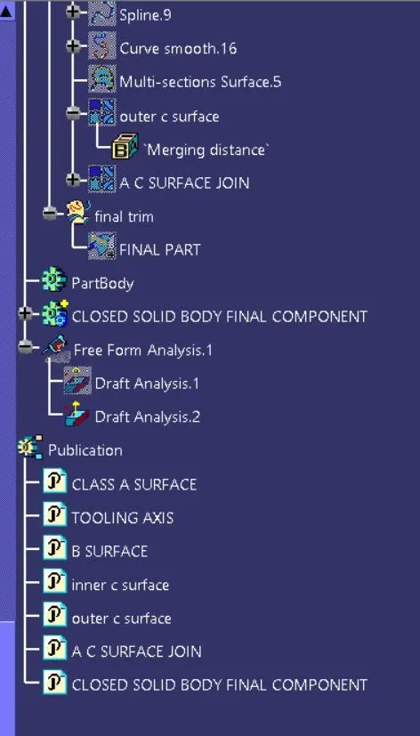
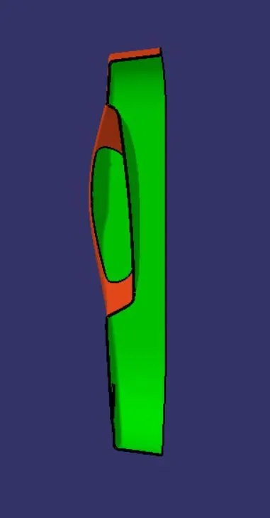
DRAFT ANALYSIS
The draft analysis technique is used to analyze whether our part model created in CAD is manufacturable based on the draft condition applied. Here the part should get easily removed from the panel dies (in case of Sheet metal part) or Mold (in case of plastic).
STEP 1
To change the view mode of material mode of the component.
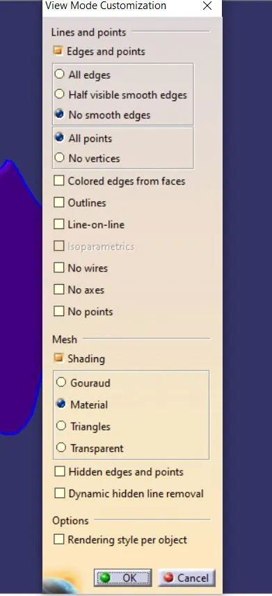
STEP 2
To click the draft analysis dialog box it will showing some icons to click the compaas icon and drag the compass to fix on the tooling axis.
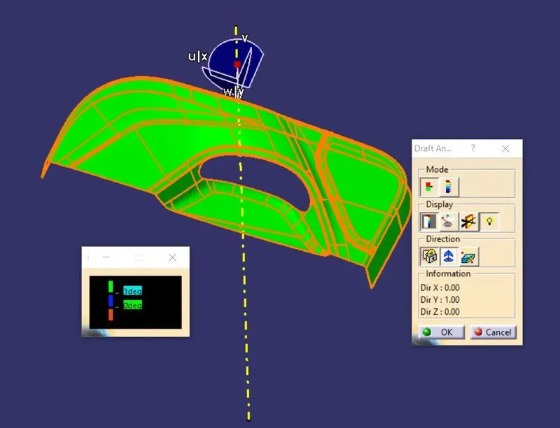
STEP 3
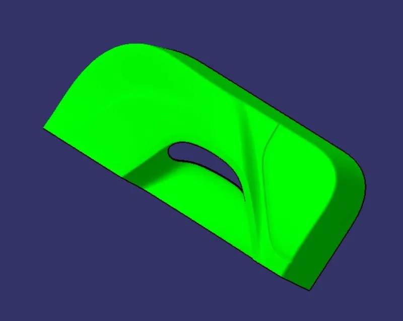
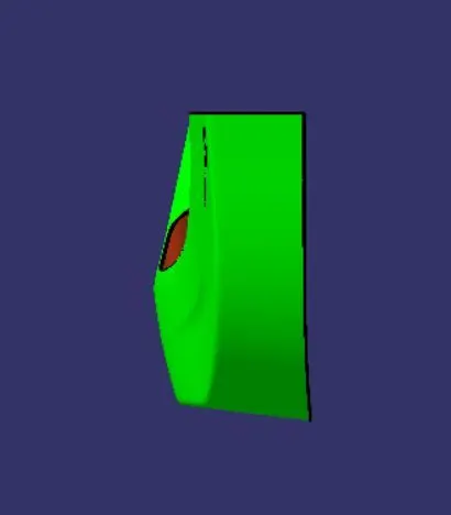
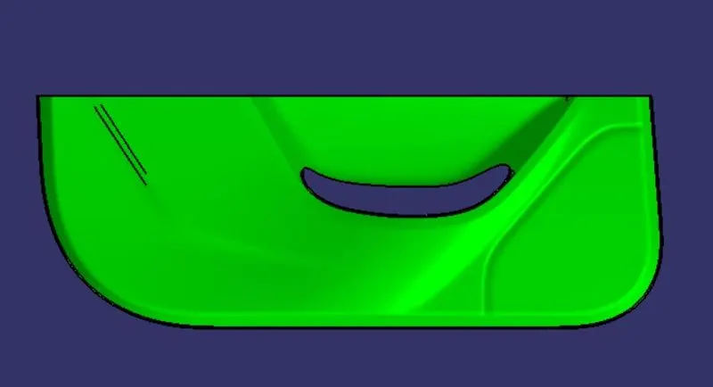
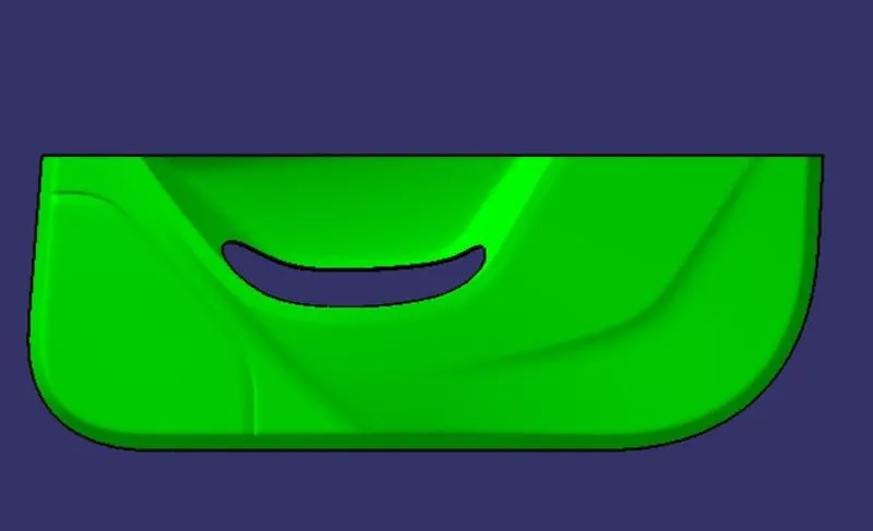
After placing the compaas on tooling axis lock the posistion and click whereever on the component it will get the result. To showing green is possitive draft.
VARIOUS ORIENTATION OF VIEWS IN DRAFT ANALYSIS THE COMPONENT
ISOMETRIC VIEW
FRONT VIEW
SIDE VIEWS
TOP VIEW