Week 8 - Challenge 5 - Door Trim Lower
CHALLENGE 4
DOOR TRIM
AIM: Create the Door Trim Plastic component through the given Class-A surface. To begin with, the tooling axis for the given Class-A Surface should be created meeting the requirements of the draft angle and at the end perform the Draft analysis on the model.
NOTE: Thickness of the component is 2.5mm
Given Class A surface
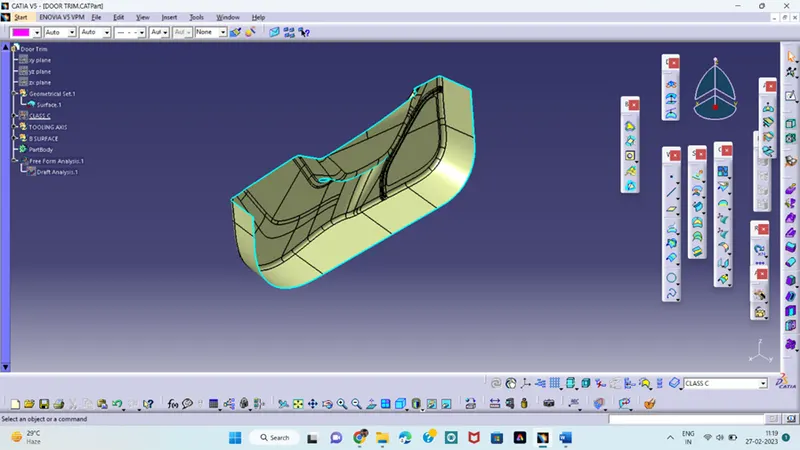
Using this class A surface will create Tooling axis, Draft analysis and the class B, Class C surface and finally use the close surface.
TOOLING AXIS:
Tooling axis is the direction in which the core and cavity opens in the tooling direction.
In this model intersection method is not possible for the tooling axis and we use directions method, in which the direction is suitable for the tooling axis.
In X direction
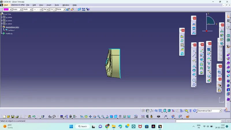
In the X direction some faces only visible and in this direction when we create the tooling axis some invisible faces shows red colour in the draft analysis it means it is not possible for the tooling direction.
In Z direction
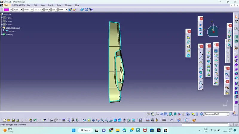
In the Z direction also only the side surface only visible and In this direction when we create the tooling axis some error will occur same as we seen the X direction. So it is also not suitable for the tooling axis.
In Y direction
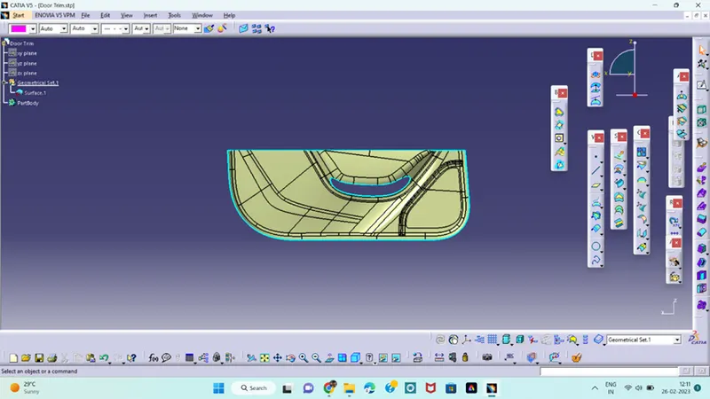
In this direction we can see the all faces and this direction is suitable for the tooling direction
First we extract the flat surface then create the point on the surface at the middle of the surface and then create a line normal to the surface.
This is the tooling axis for the component and the direction for the core and cavity open in the tooling direction
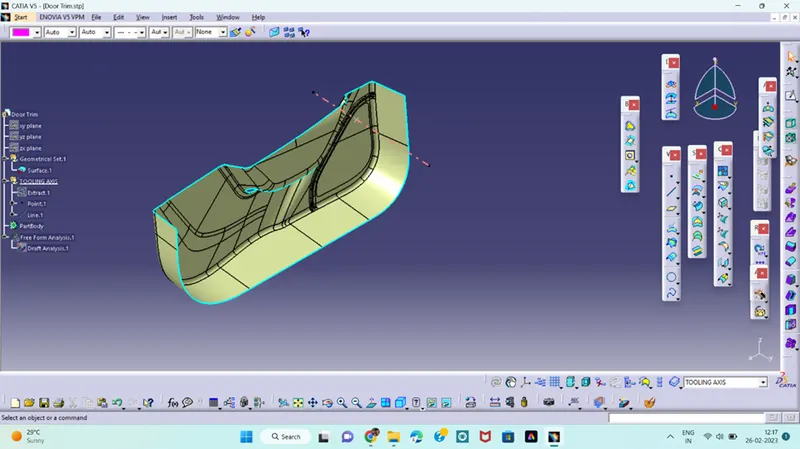
Next stage is to analyse the draft analysis for the component in the tooling axis
DRAFT ANALYSIS:
The draft analysis technique is used to analyse the whether our part model is created in CAD manufacturing based on the draft condition applied
First use the analysis option and in that click draft analysis command in that click the compass option, this compass placed over the tooling axis and fix it on. Click on the component when the compass is placed on the tooling axis, some colour changes, when it is green colour it ok for the draft and when it shows the blue or some red colour it is not suitable for the draft.
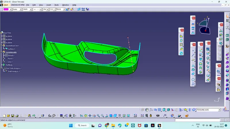
This is the final stage in draft analysis for this component and next is to create the Class B, Class C surface using Class A surface.
Class B surface:
For creation of the Class B offset the Class A surface at 2.5mm and check the direction properly in which direction we are giving the offset
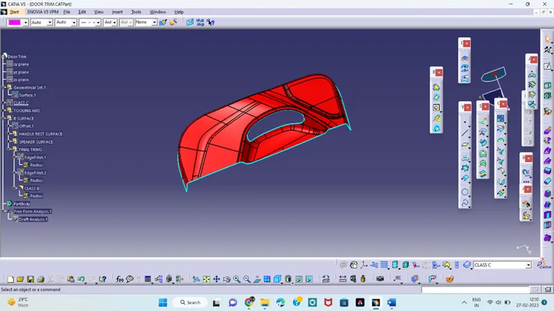
When we create the B surface check once with class A surface
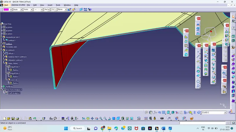
This is the exact shape of class B surface what we need and then create the class C surface using the Class surface
Class C surface:
Creation of C surface have more complexity we crate as a separate boundary for different curvatures and then join all the surfaces which created separately
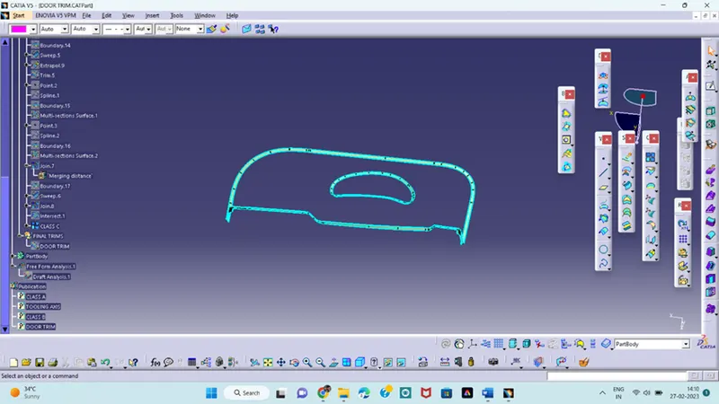
Class A and Class C surface both join them and next step is trim with the Class B surface
When trim after define in part workbench and create a close surface using close surface command.
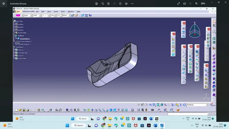
This is the final close body of a Door Trim part