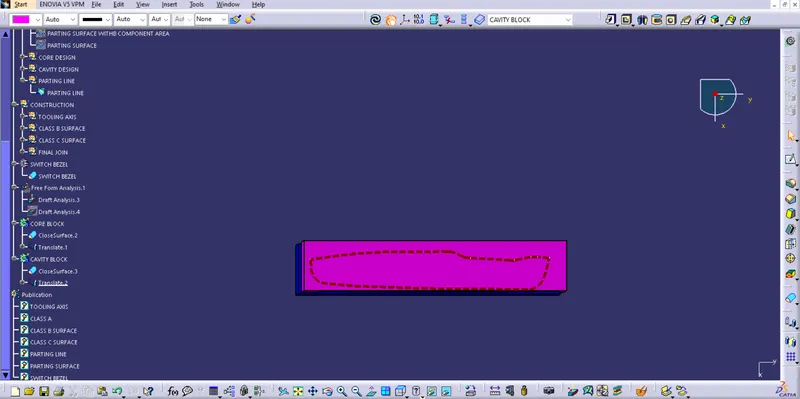
Week 8 - Challenge 5 - Core & Cavity Design
AIM
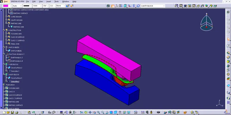
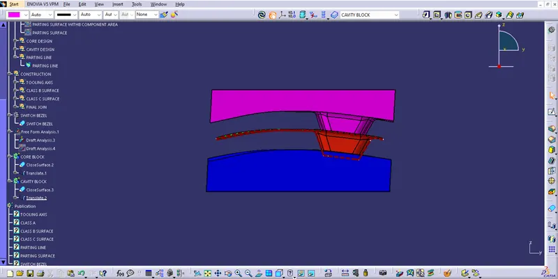
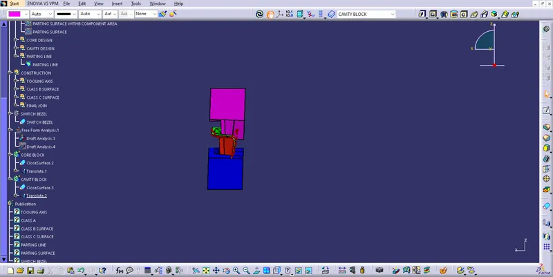
Create the Core and cavity blocks for the switch bezel.
THEORY
TOOLING AXIS:
Tooling axis is the parameter which decides whether the tool enters into moulds or not as it denotes the draft clearance angle where a moulded part is removed from the mould.
DRAFTING ANALYSIS:
The Draft Analysis command enables to detect if the part you drafted will be easily removed. This type of analysis is performed based on color ranges identifying zones on the analyzed element where the deviation from the draft direction at any point, corresponds to specified values.
PARTING SURFACE:
Injection mold has two major components the movable halve and the fixed halve, during the process these two halves to avoid the melt flow leakage and maintain certain holding pressure, the pressed surface are called Parting Surface.
PARTING LINE:
A parting line is the line of separation on the plastic part where the two halves of the plastic injection mold meet.
CORE:
The core is the male part which forms the internal shape of molding. The cavity is the female part which forms external shape of molding.
CAVITY:
The enclosed space between two mold halves which forms the shape of the desired part.
PROCEDURE
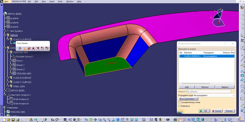
EXTRACTING
Extracting base part of the switch bezel using multiple extract tool.
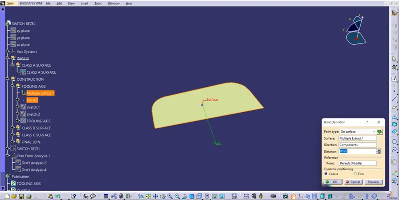
CREATING A POINT
A point is created in the extracted surface using point tool with point type as on surface.
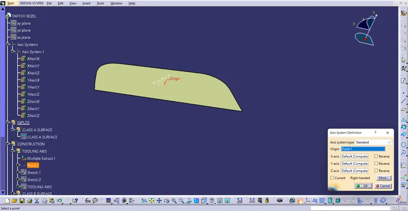
CREATING AXIS SYSTEM
Creating a new axis system on the reference point.
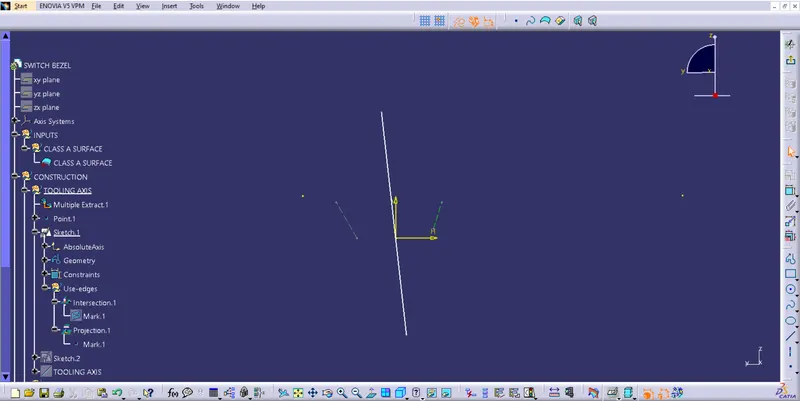
CREATING A AXIS WITH RESPECT TO SIDE WALLS
Using intersection and line tool side wall represending lines are drawn then using bisecting line tool the axis is drawn.
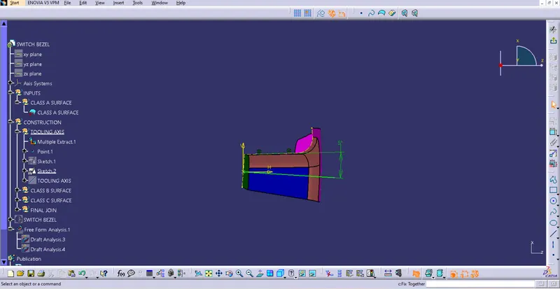
AXIS W.R.T THIRD WALL
A imaginary axis is drawn w.r.t the 3 rd wall with an angle 5 degree
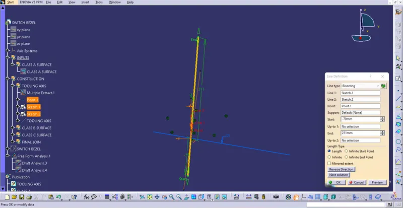
TOOLING AXIS CREATION
Final Tooling axis drawing using line tool with line type as bisecting and selecting early created 2 axises.
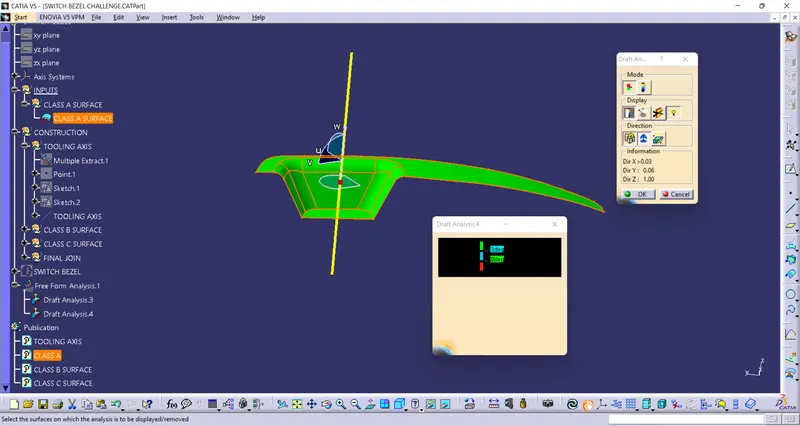
Draft analysis report Class-A
To perform draft analysis on the model:- Go to menu bar > select insert > Analysis > Feature Draft Analysis. To give the draft direction, use the compass and align Z-axis of it with the tooling axis. Once it properly aligned, lock the draft direction. A red point shown in the screen, select Base Bracket and it will show us the current of the model. Then go to display tab on draft analysis and select show Colour scale option and it will show the draft value. Set the Draft value to 3 deg under the colour scale variant and press ok.
Draft analysis report for final plastic component
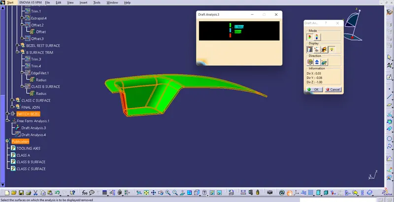
ISOMETRIC VIEW
FRONT VIEW
SIDE VIEW
TOP VIEW