Designing of Core & Cavity for Switch Bezel
CORE & CAVITY DESIGN AND DRAFT ANALYSIS OF SWITCH BEZEL
Objective:
The main aim of this report is to explain how the tooling axis was created for the given class A surface of a switch bezel design and the steps involved in draft analysis with respect to the created tooling axis. Then the procedure for creation of class B & C surface from the class A, to create solid part out of those surfaces. And then the detailed explanation for core and cavity creation for the switch bezel part.
Description:
Class A surface:
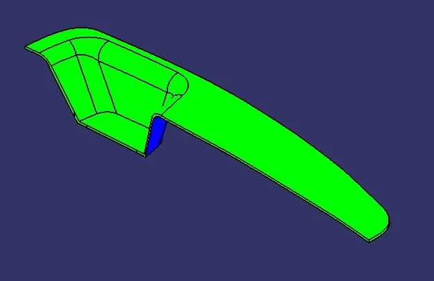
The class A surface of a switch bezel design is given to do the draft analysis and to create class B & C surface for solid part creation.
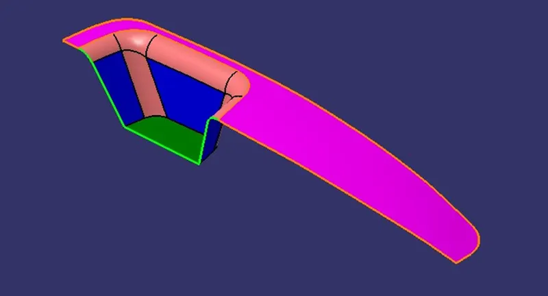
Isometric view of the given class A surface of switch bezel.
Test-1:
In this test the surface continuity of the given class A surface is examined to avoid gaps. If any gaps or discontinuity is present in the class A surface, we cannot thicken or use closed surface command to create a solid part out of it.
Joining:
By applying joining command to the class A surface, we can test the continuity of the class A surface of the given switch bezel by examining its edges.
Boundary:
By applying boundary command to the class A surface of switch bezel, we can create a boundary line of the open edges. With help of this boundary line, the continuity is tested visually.
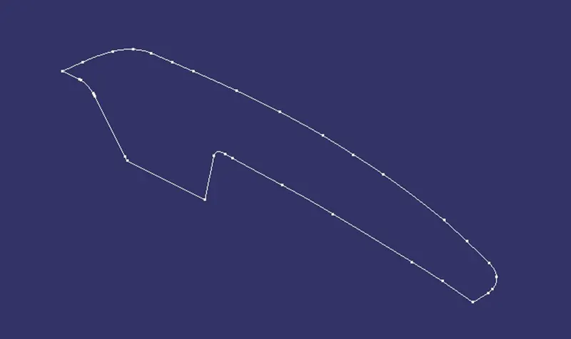
Boundary of class A surface shown in the above picture.
If any gaps or discontinuity in the class A surface is found we have to correct it for further process.
We can use either joining or boundary command for this test.
Test-2:
In this test, the tooling axis is created along the x, y and z directions, to choose the best tooling axis out of it, for reducing the tooling cost.
Intersect:
The class A surface is intersected along the yz plane and zx plane to create intersecting lines. This intersecting line is used to create lines which are considered as difficult or complex to manufacture according to the initial tooling axis and to create a bisecting line out of those lines.
Tooling axis:
Tooling axis is used to define the direction of core and cavity movement of a moulding machine according to the component to be moulded.
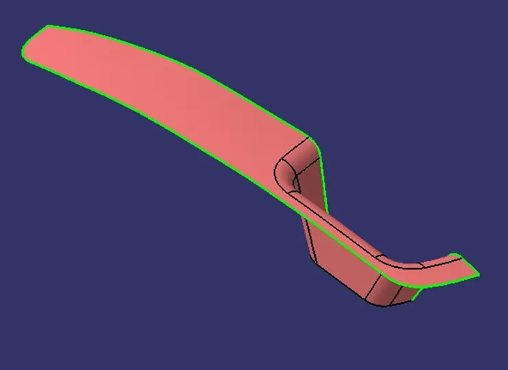
Isometric view of class A surface.
For this given class A of switch bezel, the tooling axis is created with the help of positioned sketch creation by intersecting the class A surface.
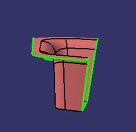
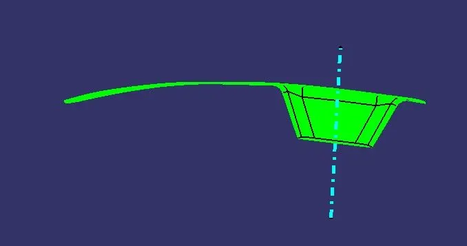
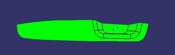
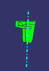
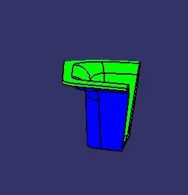
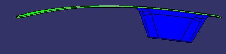
Class A surface along X axis, in this direction the pocket area with three drafted faces were not clearly visible. So, it is difficult to manufacture this component in X direction.
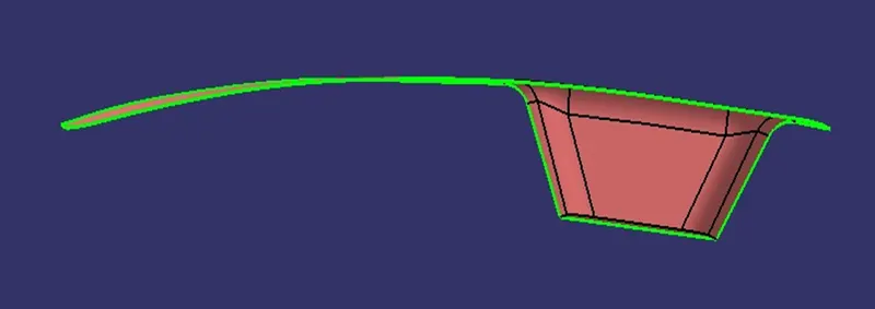
Class A surface along Y axis, in this direction the pocket area with three drafted faces were not clearly visible. So, it is difficult to manufacture this component in Y direction.
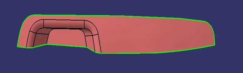
Class A surface along Z axis, in this direction the pocket area and other surfaces of the class A is clearly visible and it can be easily manufactured in Z direction.
In this case, the tooling axis is created along the z direction. Also, it is cost efficient considered with other tooling axis.
- By using the bisecting line command, a bisecting line is created with reference to those lines and point created previously. This bisecting line is considered as tooling axis.

Bisecting lines with reference to the point and lines created is shown.
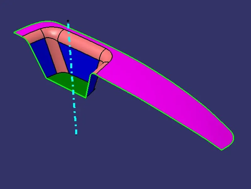
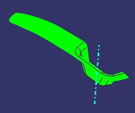
Final tooling axis is shown.
- This tooling axis decides the movement direction of core and cavity to manufacture the switch bezel part.
Draft analysis:
The draft analysis command enables you to detect if the part you drafted will be easily removed. This type of analysis is performed based on color ranges identifying zones on the analysed element where the deviation from the draft direction at any point, corresponds to specified values.
Draft analysis is carried out to check the drafts in the class A surface of switch bezel is feasible. The nominal draft for plastic components is 3º and 0.5º is the minimum draft value.
- After the creation of tooling axis, the feature draft analysis command is applied to do the analysis.
- By using the direction tool, the compass to define the new current draft direction is placed along the tooling axis. Then the draft direction is locked.
- In the display tool, the color scale is opened to give the limits for the draft analysis and then the surface is selected to test the draft for the given limits. If the color of the surface is changed to green, then the draft of the component is able to be manufactured.
- If the color of the surface is changed to red, then the class A surface is failed in draft analysis test and it is difficult to manufacture the component in cost effective manner.
- In this case, the class A surface of switch bezel is passed in the draft analysis and the part body of it can be created for further process.
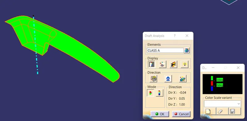
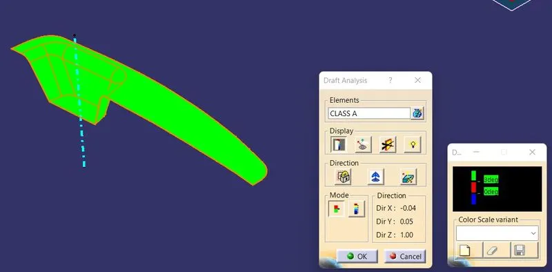
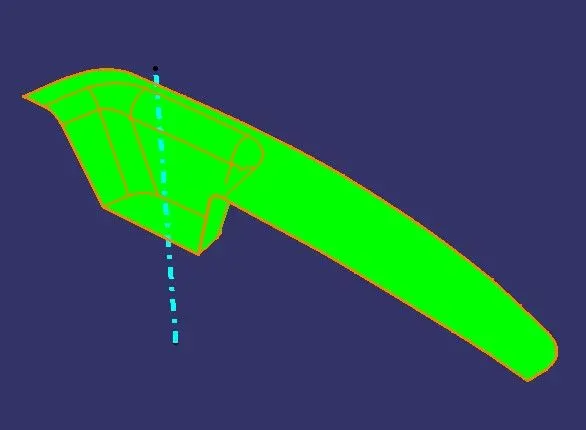
Draft analysis of the class A surface with nominal draft is shown in the picture.
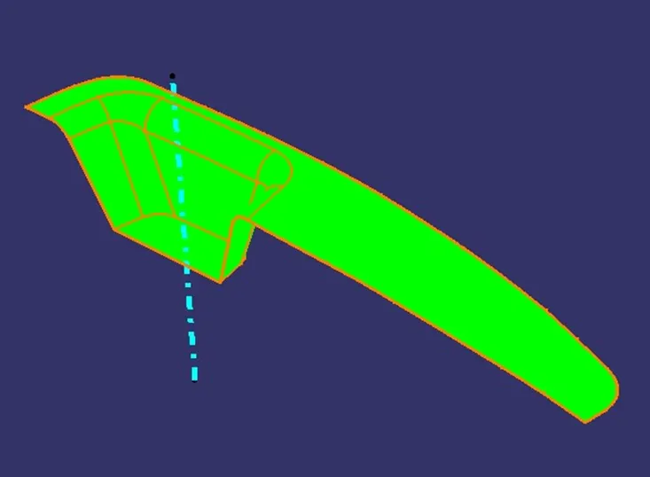
Draft analysis of the class A of switch bezel is shown.
The same procedure is followed to conduct draft analysis on the solid part also,
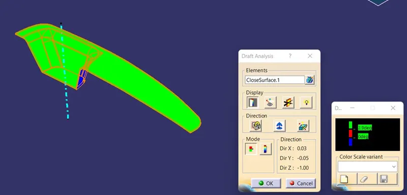
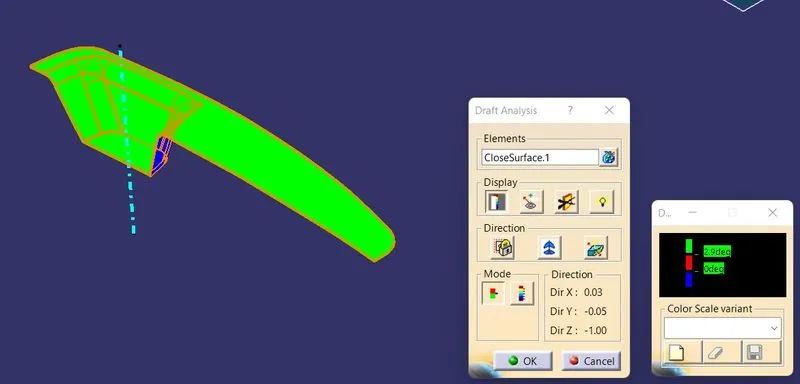
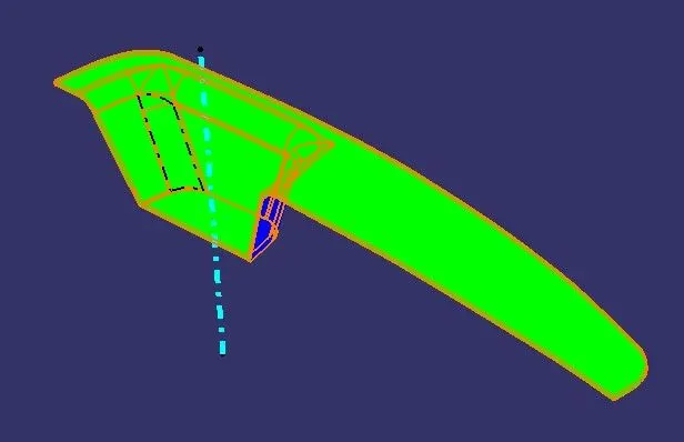
Draft analysis of the part with nominal draft is shown.
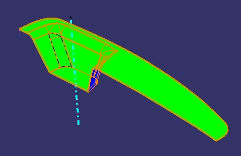
Draft analysis of switch bezel is shown.
B Surface:
B surface are said to be the engineering surface which has all the ribs and fixing elements in it. This B surface is created with reference to the given class A surface.
- After completing the draft analysis, if the class A surface is passed then the class B surface creation starts.
- Extract the necessary surface from the class A and untrim those surfaces to extrapolate it.
- After the extrapolation, trim command is applied to remove the unwanted surfaces.
- Then this surface is offset to the required thickness value and then the fillets were applied.
- This offset surface is said to be class B surface.
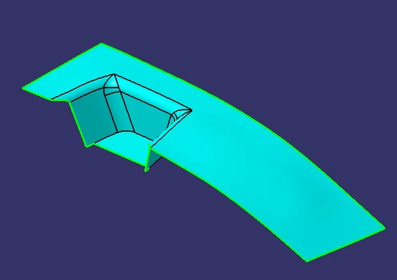
B surface shown in the above picture.
C Surface:
C surface are said to be the connecting surface of class A surface with the B surface.
- Boundary command is applied to the open edges of the class A surface to create a boundary line or multiple extract command is applied to extract the open edges.
- This boundary line or extracted line is used to create the sweep along the draft direction with enough value to overlap the B surface.
- It is said to be class C surface.
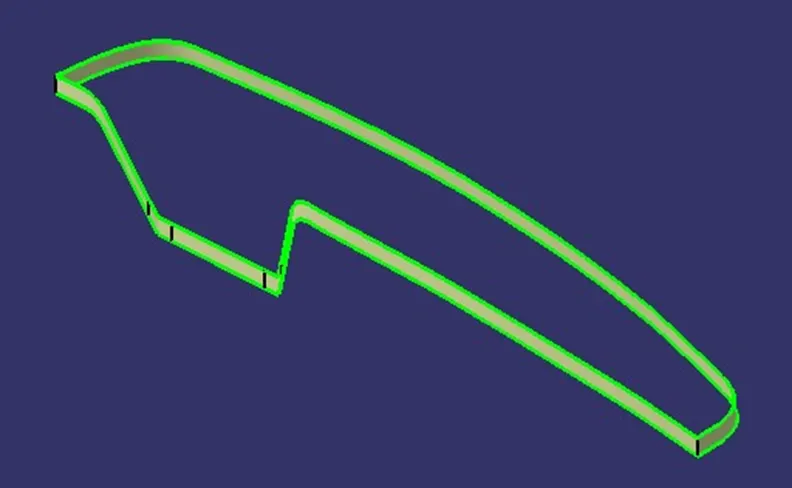
C surface shown in the above picture.
Closed surface:
Closed surface is the final surface used to create solid part by applying the closed surface command in part workbench.
- After the creation of class A, B & C surfaces, they are joined and trimmed to form the closed surface.
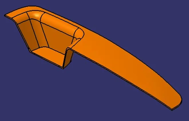
Closed surface is shown.
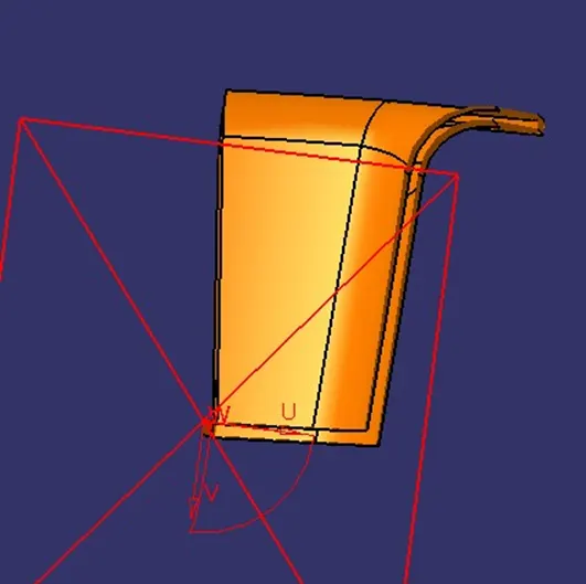
Sectioned view of closed surface.
Solid part:
Solid part is created by applying the closed surface command in part workbench to the closed surface which is created with the help of class A, B & C surfaces in the surface workbench.
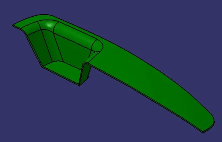
Isometric view of solid part.
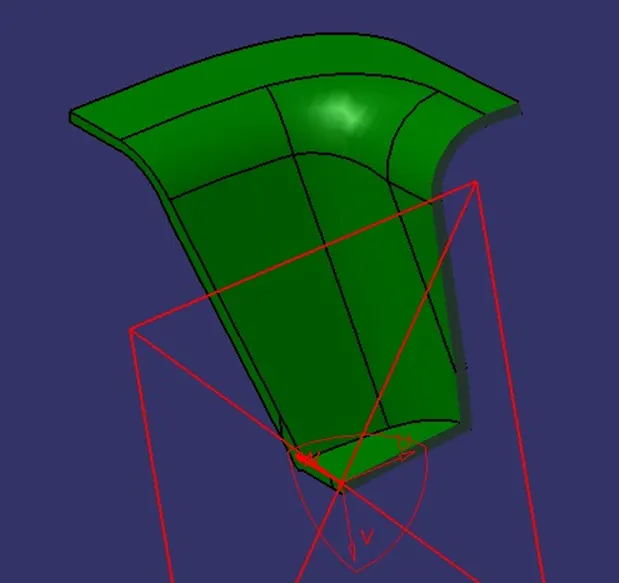
Sectioned view of switch bezel solid part.
Core & Cavity design:
Core: It is one half of the tool which is movable along the tooling axis in a mold. And it has the projection with some drafts required to manufacture the plastic components.
Cavity: It is another half of the tool which is stationary at the base of a mold with some cavity for injecting the molten plastic into it to form the required part. It has some ejector pins in it which is used to eject the molded part out of the mold.
Parting surface: This is the surface were the core and cavity meets, after the clamping process for injection.
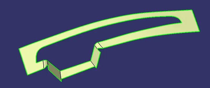
Reference image for parting surface is shown.
Parting line: It is the line were the component or part and the parting surface meets. In other words, the intersection line between the part and the parting surface is said to be a parting line.
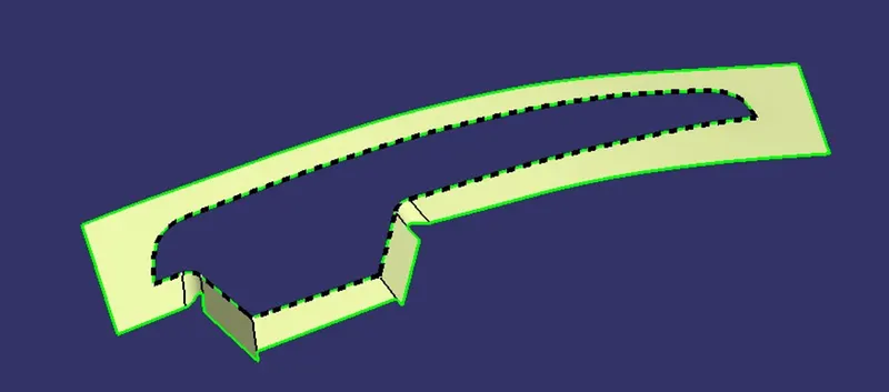
Reference image for parting line along with parting surface.
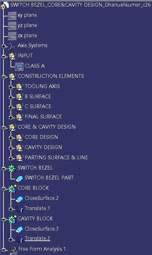
After completing the component creation for the given class A of switch bezel, then the most important part is to create the core & cavity for that component.
Let start with core creation,
- The given class A is extrapolated along its boundary to do a trim with the C surface.
- Inner side of class A and C surface is retained in that trim.
- With that trim of class A & C, another trim is performed with the B surface. Now the outer side is kept.
- Then a positioned sketch is created on the xy plane, this sketch is extruded along the tooling axis to trim the extras in that previous trim.
- After completing the required trims next step is to fill the boundary and it is joined to form an enclosed core surface.
- With this enclosed surface the core block is formed by applying the closed surface command in part workbench.
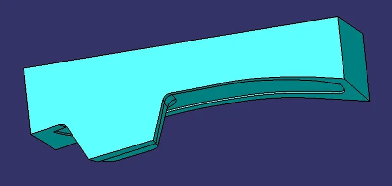
Core block.
Cavity creation,
- The cavity creation is simple than the core creation, here the positioned sketch which is created for core creation is extruded along the tooling axis.
- With this extruded surface, B surface is trimmed and the inner & bottom areas were kept.
- Then its boundaries were filled and joined to form the enclosed surface of cavity.
- This cavity surface is then created into a solid block in the part workbench with the closed surface command.
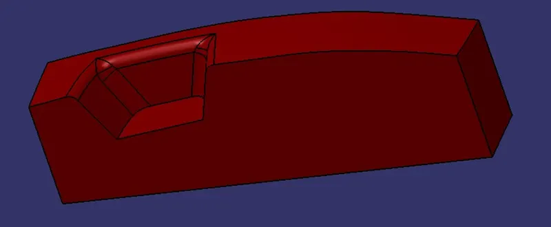
Cavity block.
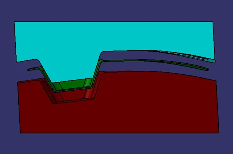
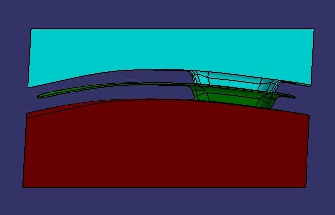
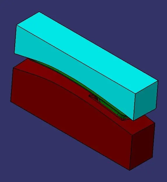
Core & cavity along with switch bezel part.
Conclusion:
The creation of tooling axis, the steps involved in draft analysis of switch bezel, class B & C surface creation, switch bezel solid part creation and core & cavity creation for the switch bezel part were explained in detail with some reference images regarding to the given class A surface of switch bezel and created surface & solid parts.